The Oasis Ambient is a beautifully-designed, Wi-Fi-enabled LED light sold by Oasis.
It features warm- and cool- LED lighting, that matches the sunrise and sunset.
Unfortunately, it does not use modern established standards for home automation, like Matter, Thread, Zigbee, or HomeKit - it uses a private, proprietary protocol.
This teardown shows you how to access the PCB, so the community can make modifications in pursuit of using the light with a private, protected, and open home automation platform.
This teardown is not a repair guide. To repair your Oasis Ambient, use our service manual.
-
-
-
Use a razor blade or plastic spudger to separate the silicone pad from the base. It is held on by an adhesive glue pad
-
-
-
Remove the sticky adhesive pad, and then use a small Philips screwdriver to remove the 4 bottom screws
-
-
-
The housing is a rough, white plastic casing, and it houses inside it a zinc casting base, which holds the braided white USB-C cable, the touch sensor, the PCB, and the mounted LED light board plus diffuser. While giving some strain relief to the USB cable by pushing more free cable through the hole, pull the mounted base away from the housing
-
-
-
Remove the copper capactive touch sensor from the housing. It is a sticker, attached to the white housing with adhesive
-
-
-
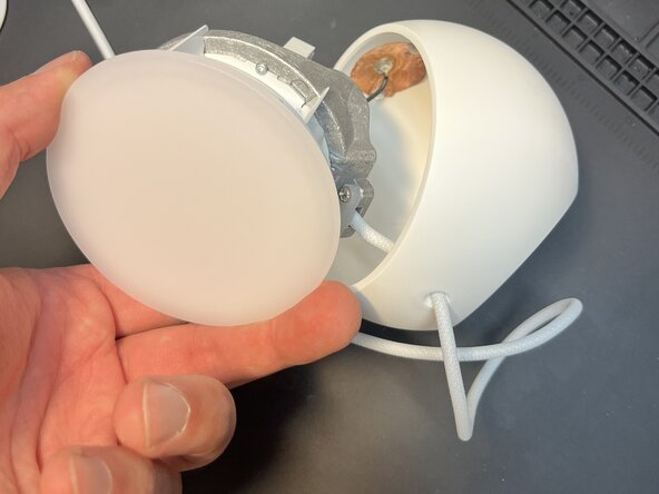
Using a spudger, or a large flathead screwdriver, Flex against the white plastic housing underneath the diffuser head. The diffuser is held in place by 4 plastic clips and some hot glue - so gently prise around the whole diffuser patiently and it will loosen and eventually pop out.
-
-
-
Unscrew the 4 Philips screws that connect the white mounting bell to the LED board
-
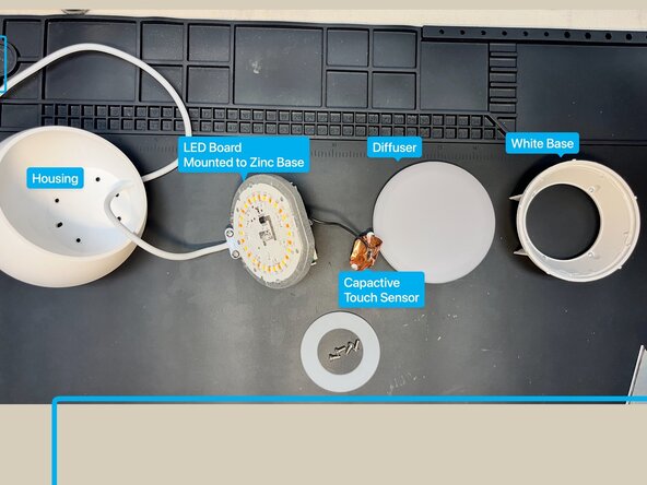
Review the pieces so far: the housing, the LED board + base, the diffuser, the white mounting bell/ring, and the silicone pad
-
-
-
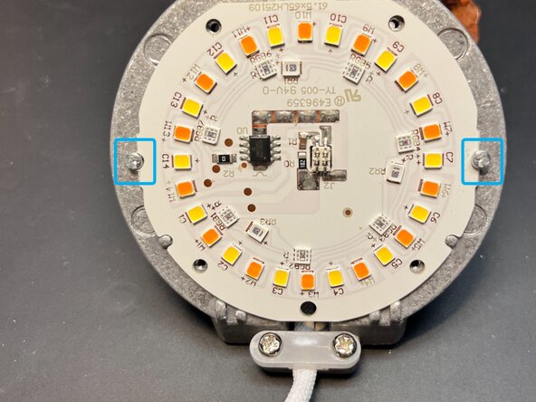
The LED board is held to the zinc base casting by 2 Philips screws. Remove them.
-
Note for later: the flat edge of the light LCB faces the top / away from the strain relief
-
There is a beige connector with 4 pins in the very center of the LED board that forms its electrical connection to the PCB
-
-
-
CAUTION! Fragile connector
-
Gently separate the LED board from the PCB by pulling straight out on the LED board. You will see the long pins from the 4-pin connector in the center of the LED board pull apart
-
-
-
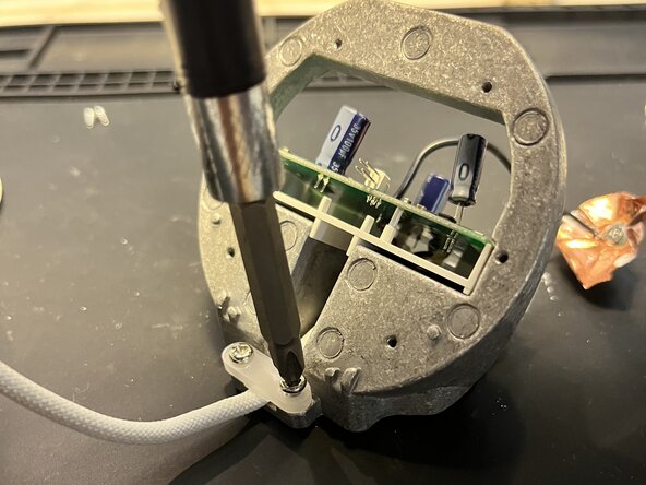
Using a Philips screwdriver, remove the USB cable's strain relief screws to free the cable from the zinc base
-
Notice that there a plastic clips in the white plastic PCB mount that hold it down. Slide those clips to the side and pop the PCB out of the mount
-
Eventually you will have the PCB free of the mount, but the cable trapped under the plastic PCB tray
-
-
-
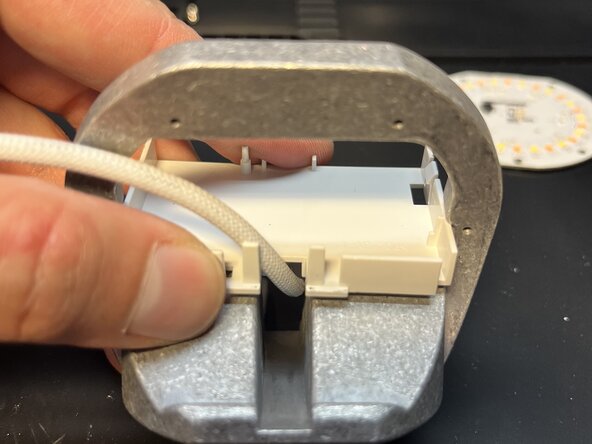
Free the white plastic PCB tray from the zinc base to allow the PCB and the USB cable to slide out from the zinc base.
-
You can use a razor blade or a spudger to separate the plastic piece from the metal slots it is mounted in
-
Push the PCB and the tray through the front of the metal base to free them
-
-
-
The Oasis Ambient is now fully disassembled
-
The white housing will entrap the USB-C cable. to further free it, you would have to desolder the USB cable from the PCB. You can push the cable through the housing to give yourself more working cable
-
-
-
The PCB features a 5V to 21V boost converter; an ESP32-C6-Mini SoC castellated module; and a 5V to 3.3V regulator to supply power to the ESP32
-
The underside of the PCB has test points for the EN pin (reset), IO9 and IO8 (boot related), 3V3, GND and RX/TX for the serial UART on the ESP32
-
-
-
The LED driver board features an LED driver chip and a wide array of Warm, Cool, and RGB LEDs.
-
The driver chip can drive 5 channels: R, G, B, Warm, Cool
-
The board is powered by +21V
-
The LED Driver IC is a SM5235E
-
-
-
In the USA mode, holding the capacitive touch sensor for several seconds resets the unit and causes the LEDs to flash and then glow blue.
-
-
-
You can solder wires to the underside of the board to access the serial UART. Use the RX and TX pins
-
If you intend to put the ESP32 into boot mode to inspect the firmware, then IO9 needs to be low (connected to GND) and IO8 needs to be high (connected to 3.3v). A typical Serial to USB couldn't provide enough power so you might want to use the USB-C to supply the external power
-
-









Embed this guide
Choose a size and copy the code below to embed this guide as a small widget on your site / forum.