Things used in this project


Story
Introduction
BD-1 is an exploration droid first appearing in "Star Wars Jedi: Fallen Order". Recently we saw BD droid in "The Book of Boba Fett" series, and it was no surprise LEGO decided to release a set featuring the droid.
I am a Star Wars fan, and one of my favorite droids is BD-1, so I decided to build it and empower it with AI. In the following short video, you can see the final result.
In a nutshell, this project will show you how to:
- build a realistic BD-1 droid from two LEGO sets and some additional parts
- use Raspberry Pi to control the LED panel
- utilise Azure Custom Vision with Raspberry Pi and camera
- control droid head based on object detection
LEGO assembly
LEGO set 75335 was released earlier this year, and the BD-1 droid you can assemble from it is approximately 30cm in height. If you want to fit Raspberry Pi and maybe even a power bank into the droids head you should build it larger, and you will need two sets. Also, with two sets you will have the opportunity to make the droid higher and more realistic.
LEGO Star Wars 75335 BD-1
Assembly will require a few additional parts, I used some parts from the LEGO Mindstorm set. Building instructions you get in the set can be used as a guide, but feel free to make modifications as you believe it is best, after all, it is your droid.
With an LED display on the back of the head and all the extra parts you add there will be extra weight, so keep in mind legs need to hold that weight, so make them strong and stable.
USB connector and power adapter take some extra space when they are plugged into the Raspberry Pi, I first tried positioning it on the side, but in the end, I had to put it horizontally in the head.
The camera can be easily placed as part of one eye, and cable goes behind it into the head and Raspberry Pi. This will also give you enough space to place a small power bank into the head.
If you feel like you need some extra LEGO bricks you can check the "Pick a Brick" shop and order specific bricks. Usually, it takes a few weeks for bricks to arrive so plan in the advance. I have also found a few 3D modeling tools for LEGO enthusiasts, but I had a feeling that creating a whole model with such tools would take a lot more time than actually assembling it.
Raspberry Pi
Raspberry Pi is pretty easy to set up, if you need any help there is a great tutorial on the official site. Once it is up and running you should open the configuration.
sudo raspi-configMake sure to enable SPI (Serial Peripheral Interface) because you will be using pins to control the LED display and motor.
Raspberry Pi configuration
I used a standard USB camera, when connected you can check it is detected with vcgencmd command.
vcgencmd get_cameraThis command should give you the result "supported=1 detected=1"which means the camera is detected and ready for use.
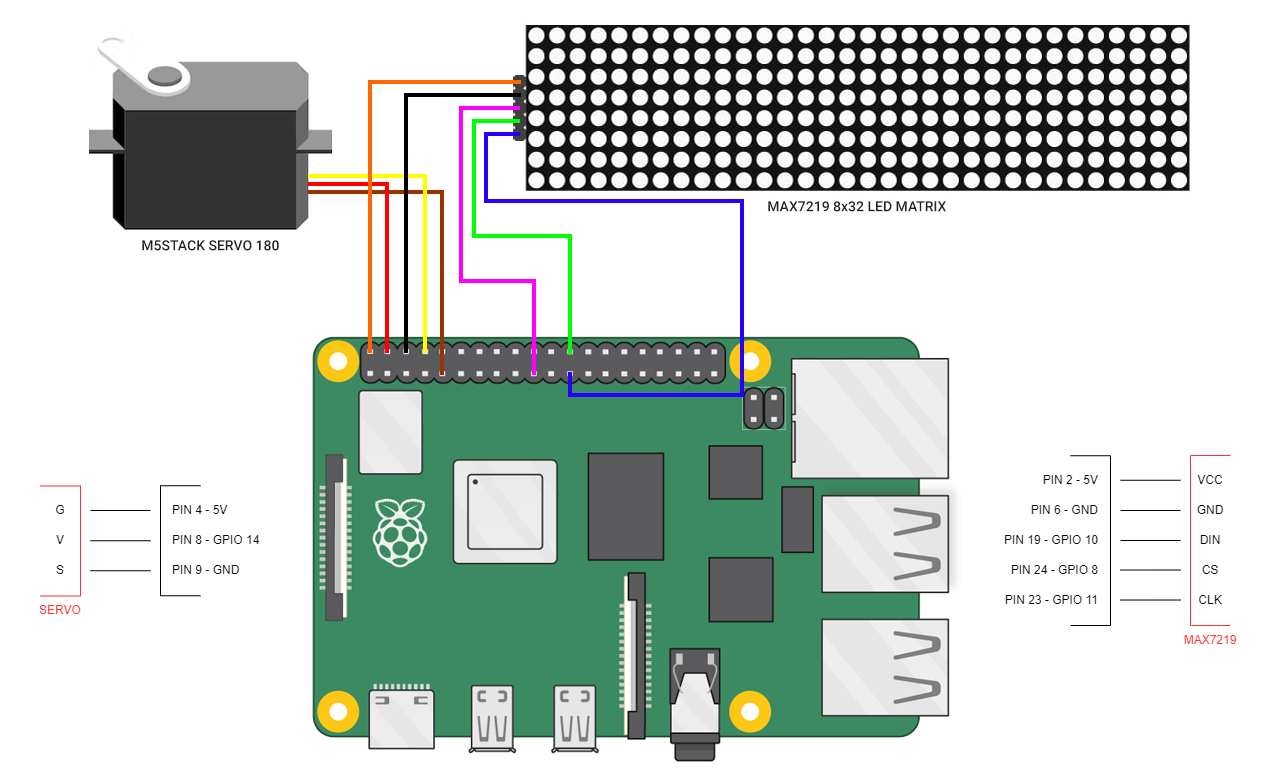
LED display
On the back of the head, I used a MAX 7219 LED display that consists of 4 modules with 64 separate LEDs. All LEDs are addressable and you can easily create patterns you like with them.
The display is connected to the Raspberry Pi in the following way:
MAX7219 LED display pin schema
Testing display with Python can be done with the following code, you can also set intensity via the code. The full example is attached and available on GitHub.
# create matrix device
serial = spi(port=0, device=0, gpio=noop())
device = max7219(serial, cascaded=n, block_orientation=block_orientation, rotate=rotate, blocks_arranged_in_reverse_order=inreverse)# set initial intensity
intensity = 16
device.contrast(intensity)
Addressing a single LED is done with the draw point command, where x and y are the exact addresses of the LED you want to light on.
draw.point((x,y), fill="white")To make back pannel lights realistic I created a pattern with a matrix, moving odd rows in one direction and even in the other.
Servo control
M5Stack has a nice servo kit with 2 motors, which I found perfect for my need. The motor is positioned on the droid's neck, turning the head left and right.
The motor is connected to Raspberry Pi pins 4, 8, and 9.
M5Stack 180° servo pin schema
With the following lines of code, you can test the motor and put it in starting position. Don't forget to run stop and cleanup in the end.
import RPi.GPIO as GPIO
from time import sleepGPIO.setmode(GPIO.BOARD)
# servo motor is connected on pin 8
GPIO.setup(8, GPIO.OUT)
servo=GPIO.PWM(8, 50)
servo.start(0)
sleep(1)
# stop and cleanup
servo.stop()
GPIO.cleanup()
With ChangeDutyCycle command motor can be placed in different positions in the following way:
# left (-90 deg position)
servo.ChangeDutyCycle(5)
sleep(1)# neutral position
servo.ChangeDutyCycle(7.5)
sleep(1)
# right (+90 deg position)
servo.ChangeDutyCycle(10)
sleep(1)
If the motor is shaking after the positioning, you can run ChangeDutyCycle with a value of zero to make it stop.
servo.ChangeDutyCycle(0)Depending on the motor's position this can be fine-tuned later if needed, once you have vision AI running and want to make the turning angle correct.
Azure Custom Vision
With the use of the camera I wanted to make droid detect objects, so I decided to use Azure Custom Vision. Create a new project, define the Resource Group, set the project type to Object Detection, and the domain to General.
Azure Custom Vision new project
Add images to your new project, you can take them with the camera connected to Raspberry Pi, or use your mobile phone if you find that is easier for you.
Azure Custom Vision adding images
Before training the model all images should be tagged correctly, clicking on the image and drawing an area on it will set the tag.
Azure Custom Vision tagging images
The process of taking images and tagging them can be time-consuming. In my free time, I work on a web-based tool that allows synthetic image generation for vision AI model training, and the tool integrates with Azure Custom Vision. With the use of a realistic 3D model, I was able to generate a few hundred images and automatically tag them in a matter of seconds. The tool is called syntheticAIdata, it is open for signups if you are interested to check it out once it gets released.
With images ready for training, you can press the "Train" button in the top right corner of the Azure Custom Vision interface, and in a few minutes, your model will be trained.
Azure Custom Vision training model
The last step needed is to publish the model in Azure Custom Vision, so you can access it via API. URL and keys are found in the project settings.
Vision AI
The vision AI model we trained is able to detect R2D2, so we want to test it out. The whole code is on GitHub, here are a few highlights.
First, we need to capture the image from the camera and we will use OpenCV. If it is not installed yet, you can install it with pip in the following way:
pip install opencv-pythonOpenCV needs to be imported into your Python code and we can capture the image.
camera = cv2.VideoCapture(0)
camera.set(cv2.CAP_PROP_FRAME_WIDTH, 320)
camera.set(cv2.CAP_PROP_FRAME_HEIGHT, 240)ret, image = camera.read()
cv2.imwrite('capture.png', image)
The image from the camera is stored in the capture.png file. The image is validated with our model and we get an array of results. In case we have one R2D2 in the image this array will have one element.
with open("capture.png", mode="rb") as captured_image:
results = predictor.detect_image("<PROJECT_ID>", "<ITERATION_NAME>", captured_image)for prediction in results.predictions:
Calculating the R2D2 location in the image is done in the following way:
locationBD1 = prediction.bounding_box.left + prediction.bounding_box.width / 2Based on the location we can turn on the motor and move the head in the desired direction.
The result of the detection can be drawn on the picture and stored with the following code:
bbox = prediction.bounding_box
result_image = cv2.rectangle(image, (int(bbox.left * 640), int(bbox.top * 480)), (int((bbox.left + bbox.width) * 640), int((bbox.top + bbox.height) * 480)), (0, 255, 0), 3)
cv2.imwrite('result.png', result_image)
If there was an object detected in the image, your result will look like this:
Vision AI model R2D2 object detection
As you will notice in the code I position BD-1 head based on 3 main positions depending on where R2D2 is. It is also possible to position it in the exact location based on the calculation listed above.
Final words
I had a lot of fun building this project, and I hope I also inspired you to build something cool. Hopefully, this project gave you some useful tips on it.
And remember: recycle your droids, save the galaxy!
Schematics