Antennas are everywhere, in numerous types and form factors, at various price points, for many markets.
Antenna Basics
Antennas transform electric currents in conductors to radiating electromagnetic fields or vice versa, typically at frequencies related to the size of the antenna. The simplest are omnidirectional meaning they work somewhat like a traditional light bulb, producing light all around the bulb.
Learn about the five essential specs you need to know when choosing an Antenna, here.
Let’s start with the humble dipole, formed by two ¼ wavelength long conductors connected to the ‘hot’ and ‘ground’ of an RF circuit. To make a 300 MHz dipole, the overall length would be 0.5 meters, i.e. two 0.25 meter arms mated to the feed point at their ends. This creates a so-called center-fed dipole antenna.
So how does such a simple structure couple an electromagnetic field around it? We’ll try to explain, but you’ll probably benefit more from watching this fantastic old school educational film (seriously it’s good).
One thing to get out of the way up front is that antennas are reciprocal, meaning that an electromagnetic field impinging on an antenna will create an electric current in the antenna required for it to radiate the same way when excited by that analogous electric current. Hence, although the term radiation implies energy leaving the antenna as electromagnetic radiation, it also describes the way a radio wave interacting with an antenna will create currents in the RF circuit.
For our purposes, let’s stick with a transmission scenario.
RF transmitters produce oscillating electric currents at the frequency they are tuned to. The form of the oscillation is a sinusoidal variation of the amplitude of the voltage, centered around zero volts. For our ½ meter dipole, a transmitter creating a 300 MHz standing wave of positive and negative currents (I) in the antenna, also creates corresponding changes in voltage (V) as determined by Ohm’s law (V=I*R). These changing currents and voltages generate electric and magnetic fields that are in time-quadrature (see the video), and travel out from the antenna.
Defense and Security Radio Systems
Most radio systems for defense and security are designed for optimal performance at 50 Ohms real impedance (no complex component). From the perspective of the transmitter, an antenna looks like a ‘reactive’ load that can be modeled as a complex combination of resistance, capacitance and inductance as a function of frequency. Antennas rarely meet this ideal 50 Ohm standard, except for narrow frequency range of operation inherent to certain designs and/or painstakingly optimized antennas — described as ‘matched.’ Indeed, an ideal dipole is a 73 Ohm radiation resistance device, while a monopole operates ideally at 37 ohms. 50 Ohm RF design is a convention to split this baby.
There are several ways to illuminate this impedance behavior, most often as a graph of Voltage Standing Wave Ratio (VSWR) which is another way to state the return loss of an RF device or antenna. See this excellent explanation or check out our blog post that makes fun of the counter-intuitive terms used.
Antenna Radiation
Now let’s explore how antennas radiate.
The relative strength of the electromagnetic field around the antenna is determined by the type of antenna and its design. For a dipole, the omnidirectional radiation of the E-field is the same in all azimuthal directions of the plane perpendicular to the antenna axis (also-called boresight), maintaining circular symmetry but diminishing to near zero in the direction of the ends of the antenna (the so-called nulls).
So, a dipole’s radiation is not quite as isotropic as a lightbulb, but pretty close. In fact, antenna engineers compare the radiation strength of a dipole to a mythical isotropic radiator, and state the ideal dipole’s boresight gain, or relative strength, as 2.15 dBi (decibels with respect to isotropic), i.e. 1.64 times more than uniform radiation in all directions as seen in this diagram.
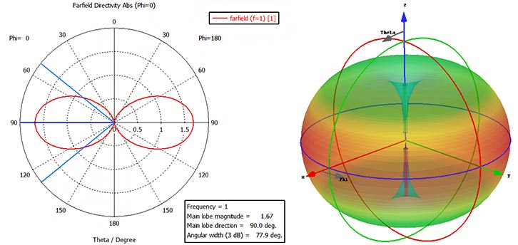
Source: https://cst2cd.acceptance.brimit.com/academia/examples/wire-dipole-antenna
Another common type of omnidirectional antenna is the monopole. By connecting the ‘hot’ side of the RF feedline to a ¼ wavelength wire and the ‘ground’ to the platform, or a so-called counterpoise, an effective compact antenna is created. The counterpoise, when not Earth itself, also known as a ground-plane, is typically composed of ¼ wavelength radials or a conductive screen or plate perpendicular to the ¼ wavelength wire.
When a monopole is constructed on a perfect perpendicular ground-plane, electromagnetically, it forms an image antenna that together mimics a dipole as shown diagrammatically here.
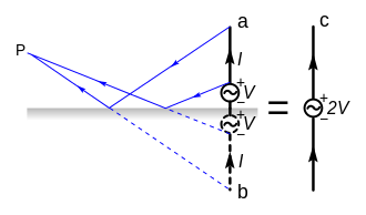 Source: https://en.wikipedia.org/wiki/Monopole_antenna
Because a monopole radiates only in the space above the ground-plane, it has twice the strength compared to a dipole, 5.15 dBi (i.e 2.15 for a dipole plus 3 dB to double to monopole power). Correspondingly, a monopole’s characteristic impedance (so-called radiation resistance) is half of a dipole.
As is often the case, the ground below a monopole is not perfect, which manifests as radiation pattern that ‘lifts’ from the horizon and reduces gain depending on the quality of the ground conductivity. See the diagram below showing a modeled HF monopole’s sensitivity to real-world ground conditions encountered by radio operators.
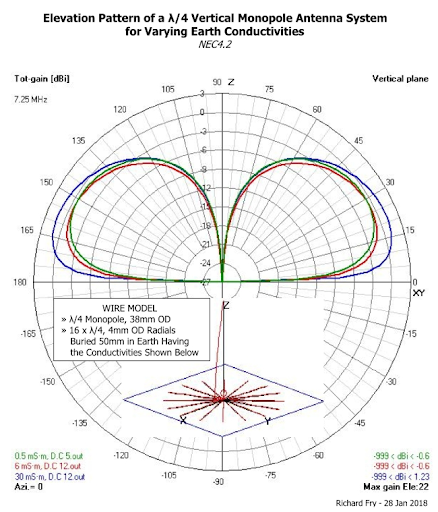
Source: https://broadcastengineering.info/viewtopic.php?t=6276
Such are the two types of omnidirectional antennas traditionally encountered in tactical communications systems. Deciding whether to choose a monopole or dipole for a particular platform and communication system depends on the concept of operations and other factors like co-siting of other antennas and the ability of the platform to form a suitable counterpoise. In general, handheld and manpack radios get monopoles, while fixed site and portable applications get dipoles. Vehicles can get either.
Finding an Omnidirectional Antenna
So you want an omnidirectional antenna. Should be easy to find what you need, right?
Maybe, but probably not -- without a fair amount of expertise and/or a list of the right questions to ask and specifications to cover. Let’s narrow things down via a series of questions.
1. Is the antenna for receive-only, or for transmitting low, moderate or high levels of power? BTW, transmit antennas can generally also receive, so you get that for free. Most tactical communications antennas fall into the moderate power (scores of watts) transceive variety.
2. What platform will the antenna mount to?
Although some omnidirectional antennas can be used on many structures, they are usually optimized for handheld, manpack, vehicle, tactical portable or fixed site platforms — but there are also naval, airborne and spacecraft omnidirectional antennas!
3. What’s the frequency of operation? And for transmit, what’s the maximum continuous power the transmitter will output; and what maximum VSWR can it tolerate?
Choosing an antenna that works for all frequencies and power levels expected is paramount for the aerial’s survival while providing the transmitter a sufficiently well-matched impedance keeps reflected power below levels that can damage its amplifier.
4. What gain and radiation characteristics are required? Relatedly, is a ground-plane dependent or independent omnidirectional antenna desired? Omnidirectional gains are typically about 0 to 2 dBi within 20 degrees above and below the horizon for antennas of standard dimensions (½ wavelength for a dipole, ¼ wavelength for a monopole). Wideband omnis can have gain as low as -20 dB at the low-end of their frequency range for practically sized structures. Some high gain omnidirectional antennas can obtain gains of 4 to 8 dBi, while their radiation patterns are compressed to ten degrees or less above and below the horizon.
Receive-only nearby field strength limits should be considered.