1. Overview of Glider
Glider is the core of the Modos Paper Dev Kit. It’s an open-source, e-ink display controller board designed to enable low-latency, high-refresh e-paper displays. Just like other display controllers, it sits between the video source (like a PC) and the screen, where it translates standard video signals into screen-specific control signals. But unlike typical e-ink solutions, Glider focuses on reducing latency to make e-ink viable for interactive applications like coding, writing, and lightweight real-time use.
The Glider README provides a comprehensive description of how e-ink works in general and how low-latency driving is implemented. So, this update will focus more on the board itself.
2. Key Design Choices
Why a Controller-less EPD Panel
E-ink panels come in two flavors: ones with an integrated controller (typically with an SPI interface) and ones that don’t. A critical design choice in the Glider was to avoid e-ink panels with built-in controllers and instead opt for an external controller. Here is a quick comparison of both types:
| Feature | Integrated Controller | External Controller |
|---|---|---|
| Size | Typically < 5" | Typically > 5" |
| Cost | Low | Higher |
| Compatibility | Compatible with most MCUs | Needs specialized controller HW/SW |
| Latency | High | Depends on controller |
| Grayscale | Limited (2–4 levels typical) | Full 16 levels |
| Suitable for | ESL, IoT, low-res apps | Monitors, e-readers, real-time use |
Integrated controllers are often quite limited in performance. Generally, they provide only 1-2 bpp framebuffer, limiting their greyscale levels. Most of these don’t support pipelined operation, reducing the maximum frame rate. Interface bandwidth is also a limiting factor, increasing the latency.
Since the goal was to create a true monitor experience (typing, coding, UI interaction), latency and visual fidelity are the top priorities. This rules out screens with integrated controllers.
Why FPGA
Microcontrollers nowadays are getting really fast. People have demonstrated controlling raw e-ink panels with fast MCUs like STM32, ESP32, RP2040, and RP2350. While these solutions are great for signage/standalone applications, MCU-based solutions are less ideal for monitor applications for the following reasons:
- Bandwidth limitations: Most MCUs don't have the necessary peripherals to receive high frame rate and high resolution video streams from an external host (PC).
- Memory limitations: On-chip SRAM is generally not large enough to hold the entire frame buffer, while the external PSRAM/SDRAM are usually not fast enough for streaming pixels.
- Processing power limitations: Embedded CPUs are simply not designed to handle a lot of pixels.
The following is a thought experiment, not something ever implemented.
Let’s consider an RP2350 as an example. The goal is to drive a 13.3" 1600x1200 panel at 60 Hz, with an external PC providing a video source.
The first step is to transmit the image from the PC to the RP2350. The most ideal way is to transmit using a conventional video interface such as VGA, DVI, or DisplayPort. Standard 1600x1200 60 Hz timing uses a pixel clock of around 125 MHz (CVT-RB-v2). On an RP2350, the PIO can be used to receive pixel data. However, the PIO cannot receive source-synchronous data. So we have to use an external PLL to clock the RP2350 synchronously with the video stream.
The next step is to process these pixels. If the RP2350 is running at 1X pixel rate (125 MHz), there is exactly one instruction time to process each pixel. This is clearly not enough. Assuming using both processor cores, and overclocking the RP2350 to 375 MHz (close to the upper limit without serious over-volting), we get six instructions per pixel, assuming close to infinite loop unrolling. Loading and storing the pixel value takes two instructions, loading and storing the pixel states takes another two instructions, so then there are only two instructions left for doing meaningful calculations on the pixel which is not even enough for doing a conditional branch based on the pixel value. So this already looks like it’s not going to work.
Then we come to storing the internal pixel states. The e-ink panel has requirements on the driving time, so it’s important to keep per-pixel context information. Assuming we’re using PSRAM for context storage, the PSRAM has a maximum frequency of 133 MHz, with a bus width of 4-bit, providing up to 66MB/s of bandwidth. With a pixel rate of 125 MHz, one read and one write per pixel, we can see that each pixel’s context cannot exceed two bits (133*2/125). This is not even enough to store a single greyscale pixel value.
In comparison, the relatively low-end Spartan 6 FPGA used in this project accepts a video stream over LVDS at 1.05 Gbps per lane, potentially dozens of operations per pixel (limited by logic resources, not frequency), and several GB/s of memory bandwidth. Using the FPGA provides a lot of flexibility.
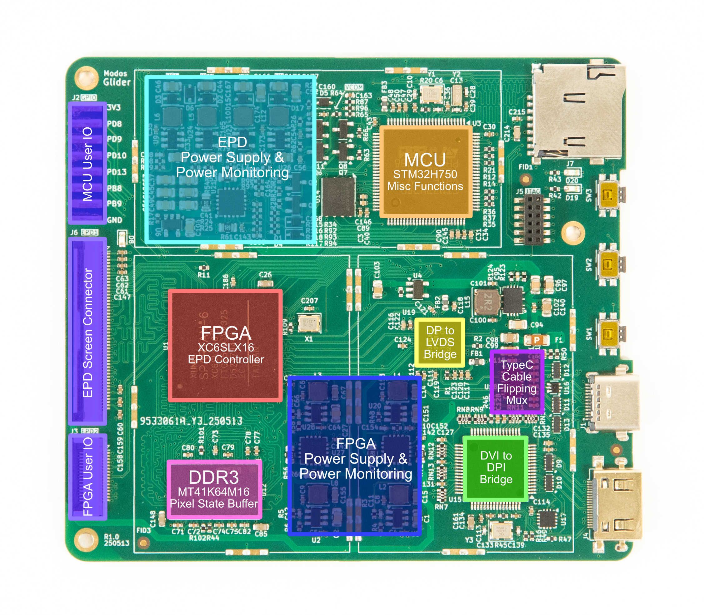
Why Spartan-6 FPGA
The Spartan-6 FPGA is a bit outdated by today’s standards. It’s a part released decades ago, only supported by now discontinued Xilinx ISE software, and superseded by Artix 7/Spartan seven years ago. But there are still good reasons to use Spartan 6:
- An integrated hard memory controller: The 7-series relies on a soft memory controller, which is inherently much more power hungry. Ultrascale+ brings back a hardened memory controller, but Spartan Ultrascale+ hasn't started shipping as of writing.
- Super-low leakage: Newer generations have much higher leakage compared to Spartan 6. With small-scale designs like this, leakage can have a significant impact on overall power consumption.
- A suspend feature: Spartan 6 has a suspend feature, which can put the FPGA into a low power mode while keeping internal logic states. This feature is absent on newer generation devices.
All three points boil down to power consumption considerations. This is not saying that Spartan-6 based design must have lower power consumption compared to 7-series or newer FPGA-based designs. This is just providing some insights into why Spartan-6 was initially chosen over other seemingly more modern FPGAs.
Why STM32H750
It might also seem weird to include a high-performance MCU when there is already a quite capable FPGA on board. The MCU does some house-keeping in the background:
- Monitors video status and reconfigures video decoders as needed
- Monitors voltages and currents to ensure they are in expected ranges
- Handles Type-C PD and DP-Alt Mode negotiation processes.
While it’s possible to implement a soft-core in the FPGA and achieve the same thing, this will add some unnecessary complexity to the project. The FPGA also lacks an integrated ADC for voltage monitoring. In many cases, a low-end STM32 can end up being cheaper than a dedicated 8-channel ADC. Given this is a development board, a higher-end STM32H750 is used here to allow more user customizations/developments.
3. From Prototype to Final Design
The development of Glider went through multiple iterations before reaching its current production-ready board.
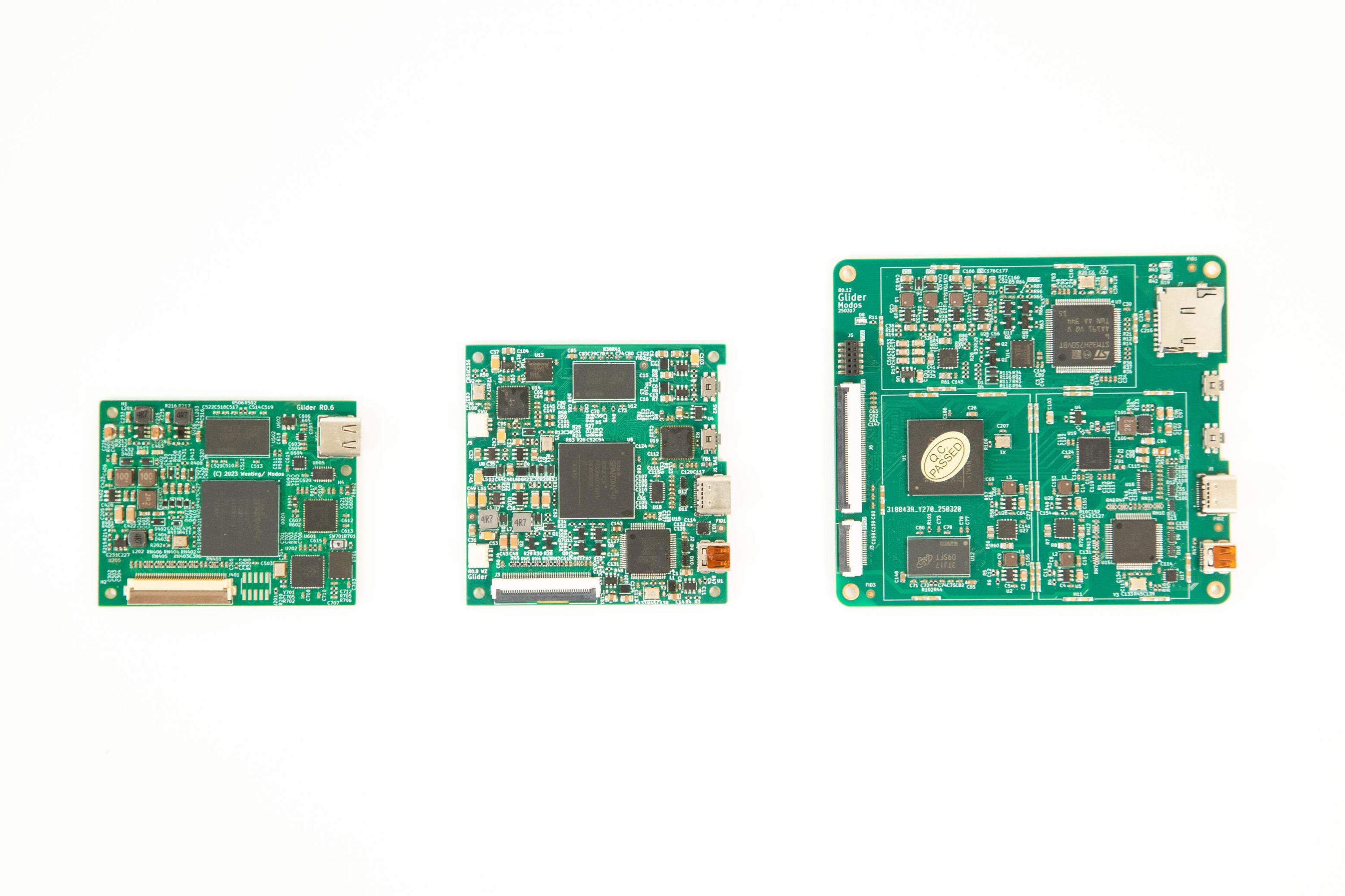
The first boards were only intended for testing FPGA logic. Initial versions (not shown here) used a full-sized DisplayPort connector instead of USB Type-C. Features and improvements were added to the board gradually. Over time, we:
- Added a microcontroller for USB communication and firmware upgrade
- Optimized DDR routing for signal integrity
- Switched to a discrete DCDC for higher current handling capability, and the original PMIC was discontinued
- Switched to a USB Type-C port over full-size DP.
- Added DVI input
- Added voltage and current monitoring to prevent screen damage in case of power supply/connector failure.
We learned some key lessons learned along the way:
- PMICs are sometimes overrated. If space is not a major concern, discrete regulators can be more cost-effective, providing higher current, and are easy to replace when the part gets discontinued (EOL).
- E-ink screens would latch-up when certain voltages are missing or when the power-up sequence is not followed. To prevent permanent damage to the screen, it's a good idea always to monitor the voltage and current.
- E-ink screens are quite power hungry when it comes to peak current. Modern high-resolution panels can consume >20 W peak.
4. Real-World Use Cases
The benefits of Glider’s design become clear in practice:
- General desktop use: Glider's pipelined controller enables low-latency display, making it more usable than existing devices. Thanks to the flexibility of the FPGA, we can implement special compensation for things like the mouse cursor.
- Writing/Coding: Glider offers a low-latency, 4-level greyscale mode specially tailored for typing
- Reading: Glider offers a low-latency monochrome + 16-level greyscale mode that allows flipping through pages quickly, while still providing high fidelity when reading.
All these optimizations are possible because we have full control of the internal workings of the controller. The FPGA can be easily reprogrammed to implement these optimizations.
Save the Date: August 28th
Teardown Session 55: Ultra Low-Latency Open Hardware E-Paper with Modos
This Thursday, August 28th, we’ll be joining Helen Leigh for a Teardown Session livestream all about how we’ve made e-paper fast. We’ll share the process, the challenges, and the techniques that let our open-hardware Paper Dev Kit hit ultra-low latency and high refresh rates.
If you haven’t already, check out our Teardown 2024 talk: Making E-Ink Go Fast.
Back the Campaign
In last week’s update, we set the goal of reaching 80%. We are now 83% funded with more than 120 backers! Every pledge, share, and suggestion is helping to shape this project and push it forward.
So, if you haven’t already, please Back the campaign on Crowd Supply. Help us reach 90% this week!
Together, we’re making e-paper faster and more open while unlocking new possibilities.