Introduction
(Updated February 2026 for PenroseKiteDart version 1.6.1)
PenroseKiteDart is a Haskell package with tools to experiment with finite tilings of Penrose’s Kites and Darts. It uses the Haskell Diagrams package for drawing tilings. As well as providing drawing tools, this package introduces tile graphs (Tgraphs) for describing finite tilings. (I would like to thank Stephen Huggett for suggesting planar graphs as a way to reperesent the tilings).
This document summarises the design and use of the PenroseKiteDart package.
PenroseKiteDart package is now available on Hackage.
The source files are available on GitHub at https://github.com/chrisreade/PenroseKiteDart.
There is a small art gallery of examples created with PenroseKiteDart here.
Index
- About Penrose’s Kites and Darts
- Using the PenroseKiteDart Package (initial set up).
- Overview of Types and Operations
- Drawing in more detail
- Forcing in more detail
- Advanced Operations
- Other Reading
1. About Penrose’s Kites and Darts
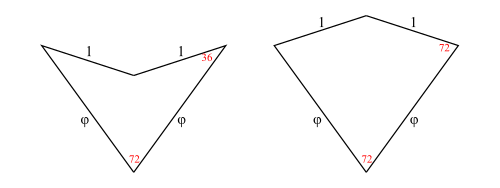
The Tiles
In figure 1 we show a dart and a kite. All angles are multiples of 


Aperiodic Infinite Tilings
What is interesting about these tiles is:
It is possible to tile the entire plane with kites and darts in an aperiodic way.
Such a tiling is non-periodic and does not contain arbitrarily large periodic regions or patches.
The possibility of aperiodic tilings with kites and darts was discovered by Sir Roger Penrose in 1974. There are other shapes with this property, including a chiral aperiodic monotile discovered in 2023 by Smith, Myers, Kaplan, Goodman-Strauss. (See the Penrose Tiling Wikipedia page for the history of aperiodic tilings)
This package is entirely concerned with Penrose’s kite and dart tilings also known as P2 tilings.
Legal Tilings
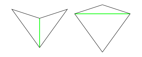
In figure 2 we add a temporary green line marking purely to illustrate a rule for making legal tilings. The purpose of the rule is to exclude the possibility of periodic tilings.
If all tiles are marked as shown, then whenever tiles come together at a point, they must all be marked or must all be unmarked at that meeting point. So, for example, each long edge of a kite can be placed legally on only one of the two long edges of a dart. The kite wing vertex (which is marked) has to go next to the dart tip vertex (which is marked) and cannot go next to the dart wing vertex (which is unmarked) for a legal tiling.
Correct Tilings
Unfortunately, having a finite legal tiling is not enough to guarantee you can continue the tiling without getting stuck. Finite legal tilings which can be continued to cover the entire plane are called correct and the others (which are doomed to get stuck) are called incorrect. This means that decomposition and forcing (described later) become important tools for constructing correct finite tilings.
2. Using the PenroseKiteDart Package
You will need the Haskell Diagrams package (See Haskell Diagrams) as well as this package (PenroseKiteDart). When these are installed, you can produce diagrams with a Main.hs module. This should import a chosen backend for diagrams such as the default (SVG) along with Diagrams.Prelude.
    module Main (main) where

    import Diagrams.Backend.SVG.CmdLine
    import Diagrams.Prelude
For Penrose’s Kite and Dart tilings, you also need to import the PKD module and (optionally) the TgraphExamples module.
    import PKD
    import TgraphExamples
Then to ouput someExample figure
    fig::Diagram B
    fig = someExample

    main :: IO ()
    main = mainWith fig
Note that the token B is used in the diagrams package to represent the chosen backend for output. So a diagram has type Diagram B. In this case B is bound to SVG by the import of the SVG backend. When the compiled module is executed it will generate an SVG file. (See Haskell Diagrams for more details on producing diagrams and using alternative backends).
3. Overview of Types and Operations
Half-Tiles
In order to implement operations on tilings (decompose in particular), we work with half-tiles. These are illustrated in figure 3 and labelled RD (right dart), LD (left dart), LK (left kite), RK (right kite). The join edges where left and right halves come together are shown with dotted lines, leaving one short edge and one long edge on each half-tile (excluding the join edge). We have shown a red dot at the vertex we regard as the origin of each half-tile (the tip of a half-dart and the base of a half-kite).
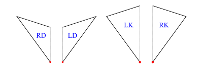
The labels are actually data constructors introduced with type operator HalfTile which has an argument type (rep) to allow for more than one representation of the half-tiles.
    data HalfTile rep
      = LD rep -- Left Dart
      | RD rep -- Right Dart
      | LK rep -- Left Kite
      | RK rep -- Right Kite
      deriving (Show,Eq)
Tgraphs
We introduce tile graphs (Tgraphs) which provide a simple planar graph representation for finite patches of tiles. For Tgraphs we first specialise HalfTile with a triple of vertices (positive integers) to make a TileFace such as RD(1,2,3), where the vertices go clockwise round the half-tile triangle starting with the origin.
    type TileFace  = HalfTile (Vertex,Vertex,Vertex)
    type Vertex    = Int  -- must be positive
The function
makeTgraph :: [TileFace] -> Tgraphthen constructs a Tgraph from a TileFace list after checking the TileFaces satisfy certain properties (described below). We also have
faces :: Tgraph -> [TileFace]to retrieve the TileFace list from a Tgraph.
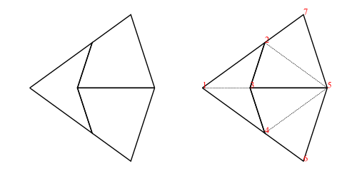
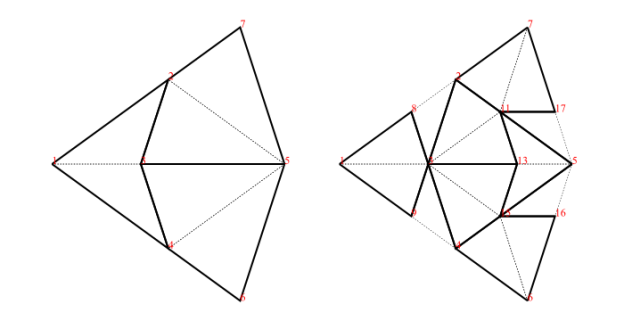
As an example, the fool (short for fool’s kite and also called an ace in the literature) consists of two kites and a dart (= 4 half-kites and 2 half-darts):
    fool :: Tgraph
    fool = makeTgraph [RD (1,2,3), LD (1,3,4)   -- right and left dart
                      ,LK (5,3,2), RK (5,2,7)   -- left and right kite
                      ,RK (5,4,3), LK (5,6,4)   -- right and left kite
                      ]
To produce a diagram, we simply draw the Tgraph
    foolFigure :: Diagram B
    foolFigure = draw fool
which will produce the diagram on the left in figure 4.
Alternatively,
    foolFigure :: Diagram B
    foolFigure = labelled drawj fool
will produce the diagram on the right in figure 4 (showing vertex labels and dashed join edges).
When any (non-empty) Tgraph is drawn, a default orientation and scale are chosen based on the lowest numbered join edge. This is aligned on the positive x-axis with length 1 (for darts) or length
Tgraph Properties
Tgraphs are actually implemented as
    newtype Tgraph = Tgraph [TileFace]
                     deriving (Show)
but the data constructor Tgraph is not exported to avoid accidentally by-passing checks for the required properties. The properties checked by makeTgraph ensure the Tgraph represents a legal tiling as a planar graph with positive vertex numbers, and that the collection of half-tile faces are both connected and have no crossing boundaries (see note below). Finally, there is a check to ensure two or more distinct vertex numbers are not used to represent the same vertex of the graph (a touching vertex check). An error is raised if there is a problem.
Note: If the TileFaces are faces of a planar graph there will also be exterior (untiled) regions, and in graph theory these would also be called faces of the graph. To avoid confusion, we will refer to these only as exterior regions, and unless otherwise stated, face will mean a TileFace. We can then define the boundary of a list of TileFaces as the edges of the exterior regions. There is a crossing boundary if the boundary crosses itself at a vertex. We exclude crossing boundaries from Tgraphs because they prevent us from calculating relative positions of tiles locally and create touching vertex problems.
For convenience, in addition to makeTgraph, we also have
    makeUncheckedTgraph :: [TileFace] -> Tgraph
    checkedTgraph   :: [TileFace] -> Tgraph
The first of these (performing no checks) is useful when you know the required properties hold. The second performs the same checks as makeTgraph except that it omits the touching vertex check. This could be used, for example, when making a Tgraph from a sub-collection of TileFaces of another Tgraph.
Main Tiling Operations
There are three key operations on finite tilings, namely
    decompose :: Tgraph -> Tgraph
    force     :: Tgraph -> Tgraph
    compose   :: Tgraph -> Tgraph
Decompose
Decomposition (also called deflation) works by splitting each half-tile into either 2 or 3 new (smaller scale) half-tiles, to produce a new tiling. The fact that this is possible, is used to establish the existence of infinite aperiodic tilings with kites and darts. Since our Tgraphs have abstracted away from scale, the result of decomposing a Tgraph is just another Tgraph. However if we wish to compare before and after with a drawing, the latter should be scaled by a factor 
We can, of course, iterate decompose to produce an infinite list of finer and finer decompositions of a Tgraph
    decompositions :: Tgraph -> [Tgraph]
    decompositions = iterate decompose
Force
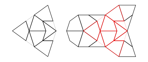
Force works by adding any TileFaces on the boundary edges of a Tgraph which are forced. That is, where there is only one legal choice of TileFace addition consistent with the seven possible vertex types. Such additions are continued until either (i) there are no more forced cases, in which case a final (forced) Tgraph is returned, or (ii) the process finds the tiling is stuck, in which case an error is raised indicating an incorrect tiling. [In the latter case, the argument to force must have been an incorrect tiling, because the forced additions cannot produce an incorrect tiling starting from a correct tiling.]
An example is shown in figure 6. When forced, the Tgraph on the left produces the result on the right. The original is highlighted in red in the result to show what has been added.
Compose
Composition (also called inflation) is an opposite to decompose but this has complications for finite tilings, so it is not simply an inverse. (See Graphs,Kites and Darts and Theorems for more discussion of the problems). Figure 7 shows a Tgraph (left) with the result of composing (right) where we have also shown (in pale green) the faces of the original that are not included in the composition – the remainder faces.
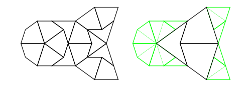
Under some circumstances composing can fail to produce a Tgraph because there are crossing boundaries in the resulting TileFaces. However, we have established that
- If
gis a forcedTgraph, thencompose gis defined and it is also a forcedTgraph.
Try Results
It is convenient to use types of the form Try a for results where we know there can be a failure. For example, compose can fail if the result does not pass the connected and no crossing boundary check, and force can fail if its argument is an incorrect Tgraph. In situations when you would like to continue some computation rather than raise an error when there is a failure, use a try version of a function.
    tryCompose :: Tgraph -> Try Tgraph
    tryForce   :: Tgraph -> Try Tgraph
We define Try as a synonym for Either ShowS (which is a monad) in module Tgraph.Try.
type Try a = Either ShowS a(Note ShowS is String -> String). Successful results have the form Right r (for some correct result r) and failure results have the form Left (s<>) (where s is a String describing the problem as a failure report).
The function
    runTry:: Try a -> a
    runTry = either error id
will retrieve a correct result but raise an error for failure cases. This means we can always derive an error raising version from a try version of a function by composing with runTry.
    force = runTry . tryForce
    compose = runTry . tryCompose
Elementary Tgraph and TileFace Operations
The module Tgraph.Prelude defines elementary operations on Tgraphs relating vertices, directed edges, and faces. We describe a few of them here.
When we need to refer to particular vertices of a TileFace we use
    originV :: TileFace -> Vertex -- the first vertex - red dot in figure 2
    oppV    :: TileFace -> Vertex -- the vertex at the opposite end of the join edge from the origin
    wingV   :: TileFace -> Vertex -- the vertex not on the join edge
A directed edge is represented as a pair of vertices.
type Dedge = (Vertex,Vertex)So (a,b) is regarded as a directed edge from a to b.
When we need to refer to particular edges of a TileFace we use
    joinE  :: TileFace -> Dedge  -- shown dotted in figure 2
    shortE :: TileFace -> Dedge  -- the non-join short edge
    longE  :: TileFace -> Dedge  -- the non-join long edge
which are all directed clockwise round the TileFace. In contrast, joinOfTile is always directed away from the origin vertex, so is not clockwise for right darts or for left kites:
    joinOfTile:: TileFace -> Dedge
    joinOfTile face = (originV face, oppV face)
In the special case that a list of directed edges is symmetrically closed [(b,a) is in the list whenever (a,b) is in the list] we can think of this as an edge list rather than just a directed edge list.
For example,
internalEdges :: Tgraph -> [Dedge]produces an edge list, whereas
boundary :: Tgraph -> [Dedge]produces single directions. Each directed edge in the resulting boundary will have a TileFace on the left and an exterior region on the right. The function
dedges :: Tgraph -> [Dedge]produces all the directed edges obtained by going clockwise round each TileFace so not every edge in the list has an inverse in the list.
Note: There is now a class HasFaces (introduced in version 1.4) which includes instances for both Tgraph and [TileFace] and others. This allows some generalisations. For example
    faces         :: HasFaces a => a -> [TileFace]
    internalEdges :: HasFaces a => a -> [Dedge]
    boundary      :: HasFaces a => a -> [Dedge]
    dedges        :: HasFaces a => a -> [Dedge]
    nullFaces     :: HasFaces a => a -> Bool
Patches (Scaled and Positioned Tilings)
Behind the scenes, when a Tgraph is drawn, each TileFace is converted to a Piece. A Piece is another specialisation of HalfTile using a two dimensional vector to indicate the length and direction of the join edge of the half-tile (from the originV to the oppV), thus fixing its scale and orientation. The whole Tgraph then becomes a list of located Pieces called a Patch.
    type Piece = HalfTile (V2 Double)
    type Patch = [Located Piece]
Piece drawing functions derive vectors for other edges of a half-tile piece from its join edge vector. In particular (in the TileLib module) we have
    drawPiece :: Piece -> Diagram B
    darawjPiece :: Piece -> Diagram B
    fillPieceDK :: Colour Double -> Colour Double -> Piece -> Diagram B
where the first draws the non-join edges of a Piece, the second does the same but adds a faint dashed line for the join edge, and the third takes two colours – one for darts and one for kites, which are used to fill the piece as well as using drawPiece.
Patch is an instance of class Transformable so a Patch can be scaled, rotated, and translated.
Vertex Patches
It is useful to have an intermediate form between Tgraphs and Patches, that contains information about both the location of vertices (as 2D points), and the abstract TileFaces. This allows us to introduce labelled drawing functions (to show the vertex labels) which we then extend to Tgraphs. We call the intermediate form a VPatch (short for Vertex Patch).
    type VertexLocMap = IntMap.IntMap (Point V2 Double)
    data VPatch = VPatch {vLocs :: VertexLocMap,  vpFaces::[TileFace]} deriving Show
and
makeVP :: Tgraph -> VPatchcalculates vertex locations using a default orientation and scale.
VPatch is made an instance of class Transformable so a VPatch can also be scaled and rotated.
One essential use of this intermediate form is to be able to draw a Tgraph with labels, rotated but without the labels themselves being rotated. We can simply convert the Tgraph to a VPatch, and rotate that before drawing with labels.
labelled draw (rotate someAngle (makeVP g))We can also align a VPatch using vertex labels.
alignXaxis :: (Vertex, Vertex) -> VPatch -> VPatch So if g is a Tgraph with vertex labels a and b we can align it on the x-axis with a at the origin and b on the positive x-axis (after converting to a VPatch), instead of accepting the default orientation.
labelled draw (alignXaxis (a,b) (makeVP g))Another use of VPatches is to share the vertex location map when drawing only subsets of the faces (see Overlaid examples in the next section).
4. Drawing in More Detail
Class Drawable
There is a class Drawable with instances Tgraph, VPatch, Patch. When the token B is in scope standing for a fixed backend then we can assume
    draw   :: Drawable a => a -> Diagram B  -- draws non-join edges
    drawj  :: Drawable a => a -> Diagram B  -- as with draw but also draws dashed join edges
    fillDK :: Drawable a => Colour Double -> Colour Double -> a -> Diagram B -- fills with colours
where fillDK clr1 clr2 will fill darts with colour clr1 and kites with colour clr2 as well as drawing non-join edges.
These are the main drawing tools. However they are actually defined for any suitable backend b so have more general types.
(Update Sept 2024) From version 1.1 onwards of PenroseKiteDart, these are
    draw ::   (Drawable a, OKBackend b) =>
              a -> Diagram b
    drawj ::  (Drawable a, OKBackend) b) =>
              a -> Diagram b
    fillDK :: (Drawable a, OKBackend b) =>
              Colour Double -> Colour Double -> a -> Diagram b
where the class OKBackend is a check to ensure a backend is suitable for drawing 2D tilings with or without labels.
In these notes we will generally use the simpler description of types using B for a fixed chosen backend for the sake of clarity.
The drawing tools are each defined via the class function drawWith using Piece drawing functions.
    class Drawable a where
        drawWith :: (Piece -> Diagram B) -> a -> Diagram B

    draw = drawWith drawPiece
    drawj = drawWith drawjPiece
    fillDK clr1 clr2 = drawWith (fillPieceDK clr1 clr2)
To design a new drawing function, you only need to implement a function to draw a Piece, (let us call it newPieceDraw)
newPieceDraw :: Piece -> Diagram BThis can then be elevated to draw any Drawable (including Tgraphs, VPatches, and Patches) by applying the Drawable class function drawWith:
    newDraw :: Drawable a => a -> Diagram B
    newDraw = drawWith newPieceDraw
Class DrawableLabelled
Class DrawableLabelled is defined with instances Tgraph and VPatch, but Patch is not an instance (because this does not retain vertex label information).
    class DrawableLabelled a where
        labelColourSize :: Colour Double -> Measure Double -> (Patch -> Diagram B) -> a -> Diagram B
So labelColourSize c m modifies a Patch drawing function to add labels (of colour c and size measure m). Measure is defined in Diagrams.Prelude with pre-defined measures tiny, verySmall, small, normal, large, veryLarge, huge. For most of our diagrams of Tgraphs, we use red labels and we also find small is a good default size choice, so we define
    labelSize :: DrawableLabelled a => Measure Double -> (Patch -> Diagram B) -> a -> Diagram B
    labelSize = labelColourSize red

    labelled :: DrawableLabelled a => (Patch -> Diagram B) -> a -> Diagram B
    labelled = labelSize small
and then labelled draw, labelled drawj, labelled (fillDK clr1 clr2) can all be used on both Tgraphs and VPatches as well as (for example) labelSize tiny draw, or labelCoulourSize blue normal drawj.
Further drawing functions
There are a few extra drawing functions built on top of the above ones. The function smart is a modifier to add dashed join edges only when they occur on the boundary of a Tgraph
smart :: (VPatch -> Diagram B) -> Tgraph -> Diagram BSo smart vpdraw g will draw dashed join edges on the boundary of g before applying the drawing function vpdraw to the VPatch for g. For example the following all draw dashed join edges only on the boundary for a Tgraph g
    smart draw g
    smart (labelled draw) g
    smart (labelSize normal draw) g
When using labels, the function rotating allows a Tgraph to be drawn rotated without rotating the labels.
    rotating :: Angle Double -> (VPatch -> a) -> Tgraph -> a
    rotating angle vpdraw = vpdraw . rotate angle . makeVP
So for example,
rotating (90@@deg) (labelled draw) gmakes sense for a Tgraph g. Of course if there are no labels we can simply use
rotate (90@@deg) (draw g)Similarly aligning allows a Tgraph to be aligned on the X-axis using a pair of vertex numbers before drawing.
    aligning :: (Vertex,Vertex) -> (VPatch -> a) -> Tgraph -> a
    aligning (a,b) vpdraw = vpdraw . alignXaxis (a,b) . makeVP
So, for example, if Tgraph g has vertices a and b, both
    aligning (a,b) draw g
    aligning (a,b) (labelled draw) g
make sense. Note that the following two examples are wrong. Even though they type check, they re-orient g without repositioning the boundary joins.
    smart (labelled draw . rotate angle) g      -- WRONG
    smart (labelled draw . alignXaxis (a,b)) g  -- WRONG
Instead use
    smartRotating angle (labelled draw) g
    smartAligning (a,b) (labelled draw) g
where
    smartRotatinge :: Angle Double -> (VPatch -> Diagram B) -> Tgraph -> Diagram B
    smartAligning  :: (Vertex,Vertex) -> (VPatch -> Diagram B) -> Tgraph -> Diagram B
are defined using
smartOn :: Tgraph -> (VPatch -> Diagram B) -> VPatch -> Diagram BHere, smartOn g vpdraw vp uses the given vp for drawing boundary joins and drawing faces of g (with vpdraw) rather than converting g to a new VPatch. This assumes vp has locations for vertices in g.
Overlaid examples (location map sharing)
The function
drawForce :: Tgraph -> Diagram Bwill (smart) draw a Tgraph g in red overlaid (using <>) on the result of force g as in figure 6. Similarly
drawPCompose :: Tgraph -> Diagram Bapplied to a Tgraph g will draw the result of a partial composition of g as in figure 7. That is a drawing of compose g but overlaid with a drawing of the remainder faces of g shown in pale green.
Both these functions make use of sharing a vertex location map to get correct alignments of overlaid diagrams. In the case of drawForce g, we know that a VPatch for force g will contain all the vertex locations for g since force only adds to a Tgraph (when it succeeds). So when constructing the diagram for g we can use the VPatch created for force g instead of starting afresh. Similarly for drawPCompose g the VPatch for g contains locations for all the vertices of compose g so compose g is drawn using the VPatch for g instead of starting afresh.
The location map sharing is done with
    subFaces :: HasFaces a =>
                a -> VPatch -> VPatch
so that subFaces fcs vp is a VPatch with the same vertex locations as vp, but replacing the faces of vp with fcs. [Of course, this can go wrong if the new faces have vertices not in the domain of the vertex location map so this needs to be used with care. Any errors would only be discovered when a diagram is created.]
For cases where labels are only going to be drawn for certain faces, we need a version of subFaces which also gets rid of vertex locations that are not relevant to the faces. For this situation we have
    restrictTo:: HasFaces a =>
                 a -> VPatch -> VPatch
which filters out un-needed vertex locations from the vertex location map. Unlike subFaces, restrictTo checks for missing vertex locations, so restrictTo fcs vp raises an error if a vertex in fcs is missing from the keys of the vertex location map of vp.
5. Forcing in More Detail
The force rules
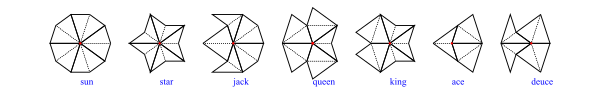
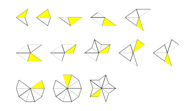
The rules used by our force algorithm are local and derived from the fact that there are seven possible vertex types as depicted in figure 8.
Our rules are shown in figure 9 (omitting mirror symmetric versions). In each case the TileFace shown yellow needs to be added in the presence of the other TileFaces shown.
Main Forcing Operations
To make forcing efficient we convert a Tgraph to a BoundaryState to keep track of boundary information of the Tgraph, and then calculate a ForceState which combines the BoundaryState with a record of awaiting boundary edge updates (an update map). Then each face addition is carried out on a ForceState, converting back when all the face additions are complete. It makes sense to apply force (and related functions) to a Tgraph, a BoundaryState, or a ForceState, so we define a class Forcible with instances Tgraph, BoundaryState, and ForceState.
This allows us to define
    force :: Forcible a => a -> a
    tryForce :: Forcible a => a -> Try a
The first will raise an error if a stuck tiling is encountered. The second uses a Try result which produces a Left string for failures and a Right a for successful result a.
There are several other operations related to forcing including
    stepForce :: Forcible a => Int -> a -> a
    tryStepForce  :: Forcible a => Int -> a -> Try a

    addHalfDart, addHalfKite :: Forcible a => Dedge -> a -> a
    tryAddHalfDart, tryAddHalfKite :: Forcible a => Dedge -> a -> Try a
The first two force (up to) a given number of steps (=face additions) and the other four add a half dart/kite on a given boundary edge.
Update Generators
An update generator is used to calculate which boundary edges can have a certain update. There is an update generator for each force rule, but also a combined (all update) generator. The force operations mentioned above all use the default all update generator (defaultAllUGen) but there are more general (with) versions that can be passed an update generator of choice. For example
    forceWith :: Forcible a => UpdateGenerator -> a -> a
    tryForceWith :: Forcible a => UpdateGenerator -> a -> Try a
In fact we defined
    force = forceWith defaultAllUGen
    tryForce = tryForceWith defaultAllUGen
We can also define
    wholeTiles :: Forcible a => a -> a
    wholeTiles = forceWith wholeTileUpdates
where wholeTileUpdates is an update generator that just finds boundary join edges to complete whole tiles.
In addition to defaultAllUGen there is also allUGenerator which does the same thing apart from how failures are reported. The reason for keeping both is that they were constructed differently and so are useful for testing.
In fact UpdateGenerators are functions that take a BoundaryState and a focus (list of boundary directed edges) to produce an update map. Each Update is calculated as either a SafeUpdate (where two of the new face edges are on the existing boundary and no new vertex is needed) or an UnsafeUpdate (where only one edge of the new face is on the boundary and a new vertex needs to be created for a new face).
    type UpdateGenerator = BoundaryState -> [Dedge] -> Try UpdateMap
    type UpdateMap = Map.Map Dedge Update
    data Update = SafeUpdate TileFace
                | UnsafeUpdate (Vertex -> TileFace)
Completing (executing) an UnsafeUpdate requires a touching vertex check to ensure that the new vertex does not clash with an existing boundary vertex. Using an existing (touching) vertex would create a crossing boundary so such an update has to be blocked.
Forcible Class Operations
The Forcible class operations are higher order and designed to allow for easy additions of further generic operations. They take care of conversions between Tgraphs, BoundaryStates and ForceStates.
    class Forcible a where
      tryFSOpWith :: UpdateGenerator -> (ForceState -> Try ForceState) -> a -> Try a
      tryChangeBoundaryWith :: UpdateGenerator -> (BoundaryState -> Try BoundaryChange) -> a -> Try a
      tryInitFSWith :: UpdateGenerator -> a -> Try ForceState
For example, given an update generator ugen and any f:: ForceState -> Try ForceState , then f can be generalised to work on any Forcible using tryFSOpWith ugen f. This is used to define both tryForceWith and tryStepForceWith.
We also specialize tryFSOpWith to use the default update generator
    tryFSOp :: Forcible a => (ForceState -> Try ForceState) -> a -> Try a
    tryFSOp = tryFSOpWith defaultAllUGen
Similarly given an update generator ugen and any f:: BoundaryState -> Try BoundaryChange , then f can be generalised to work on any Forcible using tryChangeBoundaryWith ugen f. This is used to define tryAddHalfDart and tryAddHalfKite.
We also specialize tryChangeBoundaryWith to use the default update generator
    tryChangeBoundary :: Forcible a => (BoundaryState -> Try BoundaryChange) -> a -> Try a
    tryChangeBoundary = tryChangeBoundaryWith defaultAllUGen
Note that the type BoundaryChange contains a resulting BoundaryState, the single TileFace that has been added, a list of edges removed from the boundary (of the BoundaryState prior to the face addition), and a list of the (3 or 4) boundary edges affected around the change that require checking or re-checking for updates.
The class function tryInitFSWith will use an update generator to create an initial ForceState for any Forcible. If the Forcible is already a ForceState it will do nothing. Otherwise it will calculate updates for the whole boundary. We also have the special case
    tryInitFS :: Forcible a => a -> Try ForceState
    tryInitFS = tryInitFSWith defaultAllUGen
Efficient chains of forcing operations.
Note that (force . force) does the same as force, but we might want to chain other force related steps in a calculation.
For example, consider the following combination which, after decomposing a Tgraph, forces, then adds a half dart on a given boundary edge (d) and then forces again.
    combo :: Dedge -> Tgraph -> Tgraph
    combo d = force . addHalfDart d . force . decompose
Since decompose:: Tgraph -> Tgraph, the instances of force and addHalfDart d will have type Tgraph -> Tgraph so each of these operations, will begin and end with conversions between Tgraph and ForceState. We would do better to avoid these wasted intermediate conversions working only with ForceStates and keeping only those necessary conversions at the beginning and end of the whole sequence.
This can be done using tryFSOp. To see this, let us first re-express the forcing sequence using the Try monad, so
force . addHalfDart d . forcebecomes
tryForce <=< tryAddHalfDart d <=< tryForceNote that (<=<) is the Kliesli arrow which replaces composition for Monads (defined in Control.Monad). (We could also have expressed this right to left sequence with a left to right version tryForce >=> tryAddHalfDart d >=> tryForce). The definition of combo becomes
    combo :: Dedge -> Tgraph -> Tgraph
    combo d = runTry . (tryForce <=< tryAddHalfDart d <=< tryForce) . decompose
This has no performance improvement, but now we can pass the sequence to tryFSOp to remove the unnecessary conversions between steps.
    combo :: Dedge -> Tgraph -> Tgraph
    combo d = runTry . tryFSOp (tryForce <=< tryAddHalfDart d <=< tryForce) . decompose
The sequence actually has type Forcible a => a -> Try a but when passed to tryFSOp it specialises to type ForceState -> Try ForseState. This ensures the sequence works on a ForceState and any conversions are confined to the beginning and end of the sequence, avoiding unnecessary intermediate conversions.
A limitation of forcing
To avoid creating touching vertices (or crossing boundaries) a BoundaryState keeps track of locations of boundary vertices. At around 35,000 face additions in a single force operation the calculated positions of boundary vertices can become too inaccurate to prevent touching vertex problems. In such cases it is better to use
    recalibratingForce :: Forcible a => a -> a
    tryRecalibratingForce :: Forcible a => a -> Try a
These work by recalculating all vertex positions at 20,000 step intervals to get more accurate boundary vertex positions. For example, 6 decompositions of the kingGraph has 2,906 faces. Applying force to this should result in 53,574 faces but will go wrong before it reaches that. This can be fixed by calculating either
recalibratingForce (decompositions kingGraph !!6)or using an extra force before the decompositions
force (decompositions (force kingGraph) !!6)In the latter case, the final force only needs to add 17,864 faces to the 35,710 produced by decompositions (force kingGraph) !!6.
6. Advanced Operations
Guided comparison of Tgraphs
Asking if two Tgraphs are equivalent (the same apart from choice of vertex numbers) is a an np-complete problem. However, we do have an efficient guided way of comparing Tgraphs. In the module Tgraph.Rellabelling we have
sameGraph :: (Tgraph,Dedge) -> (Tgraph,Dedge) -> BoolThe expression sameGraph (g1,d1) (g2,d2) asks if g2 can be relabelled to match g1 assuming that the directed edge d2 in g2 is identified with d1 in g1. Hence the comparison is guided by the assumption that d2 corresponds to d1.
It is implemented using
tryRelabelToMatch :: (Tgraph,Dedge) -> (Tgraph,Dedge) -> Try Tgraphwhere tryRelabelToMatch (g1,d1) (g2,d2) will either fail with a Left report if a mismatch is found when relabelling g2 to match g1 or will succeed with Right g3 where g3 is a relabelled version of g2. The successful result g3 will match g1 in a maximal tile-connected collection of faces containing the face with edge d1 and have vertices disjoint from those of g1 elsewhere. The comparison tries to grow a suitable relabelling by comparing faces one at a time starting from the face with edge d1 in g1 and the face with edge d2 in g2. (This relies on the fact that Tgraphs are connected with no crossing boundaries, and hence tile-connected.)
The above function is also used to implement
tryFullUnion:: (Tgraph,Dedge) -> (Tgraph,Dedge) -> Try Tgraphwhich tries to find the union of two Tgraphs guided by a directed edge identification. However, there is an extra complexity arising from the fact that Tgraphs might overlap in more than one tile-connected region. After calculating one overlapping region, the full union uses some geometry (calculating vertex locations) to detect further overlaps.
Finally we have
commonFaces:: (Tgraph,Dedge) -> (Tgraph,Dedge) -> [TileFace]which will find common regions of overlapping faces of two Tgraphs guided by a directed edge identification. The resulting common faces will be a sub-collection of faces from the first Tgraph. These are returned as a list as they may not be a connected collection of faces and therefore not necessarily a Tgraph.
Empires and SuperForce
In Empires and SuperForce we discussed forced boundary coverings which were used to implement both a superForce operation
superForce:: Forcible a => a -> aand operations to calculate empires.
We will not repeat the descriptions here other than to note that
forcedBoundaryECovering:: Tgraph -> [Forced Tgraph]finds boundary edge coverings after forcing a Tgraph. That is, forcedBoundaryECovering g will first force g, then (if it succeeds) finds a collection of (forced) extensions to force g such that
- each extension has the whole boundary of
force gas internal edges. - each possible addition to a boundary edge of
force g(kite or dart) has been included in the collection.
(possible here means – not leading to a stuck Tgraph when forced.) There is also
forcedBoundaryVCovering:: Tgraph -> [Forced Tgraph]which does the same except that the extensions have all boundary vertices internal rather than just the boundary edges. In both cases the result is a list of explicitly forced Tgraphs (discussed next).
Combinations and Explicitly Forced
We introduced a new type Forced (in v 1.3) to enable a forcible to be explictily labelled as being forced. For example
    forceF    :: Forcible a => a -> Forced a
    tryForceF :: Forcible a => a -> Try (Forced a)
    forgetF   :: Forced a -> a
This allows us to restrict certain functions which expect a forced argument by making this explicit.
composeF :: Forced Tgraph -> Forced TgraphThe definition makes use of theorems established in Graphs,Kites and Darts and Theorems that composing a forced Tgraph does not require a check (for connectedness and no crossing boundaries) and the result is also forced. This can then be used to define efficient combinations such as
compForce:: Tgraph -> Forced Tgraph -- compose after forcing
compForce = composeF . forceF
allCompForce:: Tgraph -> [Forced Tgraph] -- iterated (compose after force) while not emptyTgraph
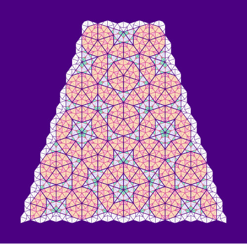
maxCompForce:: Tgraph -> Forced Tgraph -- last item in allCompForce (or emptyTgraph)Tracked Tgraphs
The type
    data TrackedTgraph = TrackedTgraph
       { tgraph  :: Tgraph
       , tracked :: [[TileFace]]
       } deriving Show
has proven useful in experimentation as well as in producing artwork with darts and kites. The idea is to keep a record of sub-collections of faces of a Tgraph when doing both force operations and decompositions. A list of the sub-collections forms the tracked list associated with the Tgraph. We make TrackedTgraph an instance of class Forcible by having force operations only affect the Tgraph and not the tracked list. The significant idea is the implementation of
decomposeTracked :: TrackedTgraph -> TrackedTgraphDecomposition of a Tgraph involves introducing a new vertex for each long edge and each kite join. These are then used to construct the decomposed faces. For decomposeTracked we do the same for the Tgraph, but when it comes to the tracked collections, we decompose them re-using the same new vertex numbers calculated for the edges in the Tgraph. This keeps a consistent numbering between the Tgraph and tracked faces, so each item in the tracked list remains a sub-collection of faces in the Tgraph.
The function
drawTrackedTgraph :: [VPatch -> Diagram B] -> TrackedTgraph -> Diagram Bis used to draw a TrackedTgraph. It uses a list of functions to draw VPatches. The first drawing function is applied to a VPatch for any untracked faces. Subsequent functions are applied to VPatches for the tracked list in order. Each diagram is beneath later ones in the list, with the diagram for the untracked faces at the bottom. The VPatches used are all restrictions of a single VPatch for the Tgraph, so will be consistent in vertex locations. When labels are used, there is also a drawTrackedTgraphRotating and drawTrackedTgraphAligning for rotating or aligning the VPatch prior to applying the drawing functions.
Note that the result of calculating empires (see Empires and SuperForce ) is represented as a TrackedTgraph. The result is actually the common faces of a forced boundary covering, but a particular element of the covering (the first one) is chosen as the background Tgraph with the common faces as a tracked sub-collection of faces. Hence we have
    empire1, empire2 :: Tgraph -> TrackedTgraph

    drawEmpire :: TrackedTgraph -> Diagram B
Figure 10 was also created using TrackedTgraphs.
7. Other Reading
Previous related blogs are:
- Diagrams for Penrose Tiles – the first blog introduced drawing
Pieces andPatches (without using Tgraphs) and provided a version of decomposing for Patches (decompPatch). - Graphs, Kites and Darts intoduced Tgraphs. This gave more details of implementation and results of early explorations. (The class
Forciblewas introduced subsequently). - Empires and SuperForce – these new operations were based on observing properties of boundaries of forced Tgraphs.
- Graphs,Kites and Darts and Theorems established some important results relating
force,compose,decompose.