Preface
I published this guide several years ago to expose my thinking and configuration to the scrutiny of networking experts and benefit less experienced users with an easy to follow but comprehensive guide. I would like to thank all those who contacted me with questions or provided feedback that contributed to making this guide what it is today. I continue to appreciate feedback on any errors, configuration or areas you think would benefit from additional clarification so please don’t hesitate to contact me by email.
Last revised 27 February 2021.
Contents
- Introduction
- Internet (WAN) connectivity overview
- Local subnet overview
- VPN provider selection
- Network topology
- Hardware selection
- Download pfSense
- Install pfSense
- Initial setup
- Interface creation and configuration
- Create and configure the VPN client
- NTP Configuration
- DNS Configuration
- Configure NAT
- Create Aliases
- Setup Firewall Rules
- Verification of functionality and performance
- References
Introduction
Several iterations ago I revised my guide towards becoming a foundational piece in a series of guides aimed at helping users create a SOHO system capable of self-hosting numerous services and supporting migration away from cloud providers to take ownership of their own data.
Although this baseline configuration remains largely the same as the previous version, there are a few areas that have been improved due to increased or refined knowledge, or as a result of the pfSense 2.5.0 release including:
- Updated OpenVPN 2.5.0 cipher configuration
- Refined DNS Resolver config to support pfBlockerNG’s DNSBL python based features
- Updated DNS servers for Guest network to support addition of 4G-LTE WAN failover
- Tweaks to ease transition for a new multi-WAN guide
- Expanded hardware section with some general recommendations
To learn more about the numberous changes included with pfSense 2.5.0, please review Netgate’s new features and changes list. OpenVPN 2.5 is incorporated into this release and its changelog is here for reference.
Internet (WAN) connectivity overview
I created this guide towards supporting typical residential and/or small office ISP bandwidth capabilities. I’ve seen good results on both cable and fibre providers with up/download capabilities in the 5/20 to asymmetric gigabit range. I’ve also heard of positive experiences on 4G LTE connections so long as the underlying connection is stable.
Local subnet overview
Although this guide focuses on building out the core local area networks (VPN, clearnet, guest and management), I’ve provided some additional details here as to the rest of my VLANs setup for some context on how I segregated my other traffic.
Unencrypted ‘clearnet’
Used for general purpose web access when an encrypted line isn’t a requirement.
General secure VPN
Primary LAN network where all traffic which exits is encrypted via OpenVPN and exits to the internet via one of several AirVPN end points.
Self-hosted subnet
I have a number of self-hosted services that reside in a VLAN and have policy routing in place to steer outbound traffic through the clearnet, AirVPN or other privately hosted OpenVPN gateways. The particular gateway is selected depending on the specific services needs and risk profile.
Guest network
Effectively this exposes my native unencrypted unsecured ISP line complete with OpenDNS name resolution. Used primarily by visitors who require internet access but also acts as a backup in case AirVPN goes down for any reason. Firewall prevents access to all local resources including user devices, file servers and core infrastructure.
Management network
Used for native hardware access to devices such as wifi access points as well as interfaces intended to be utilised only by an admin user, for example, IPMI management consoles, NUT, SNMP monitoring interfaces and headless servers.
Security cameras
Subnet which various security cameras are connected to. This subnet is heavily firewalled to prevent anyone from attempting to gain access to my home network via compromising an external cable or camera. A Windows Server 2019 VM runs my NVR software and resides in the same VLAN and subnet as the cameras themselves ensuring that the camera traffic is primarily handled by my switch rather than adding avoidable load to pfSense.
Internet of Things (IoT)
A subnet that untrusted home automation devices such as smart plugs and various sensors connect to with severely limited access to primary subnets.
Multiple DMZ’s
I run several DMZ subnets to provide isolated, de-restricted zones for numerous clients and servers which need to be accessed remotely, for example FiOS TV, Kodi video player, Plex/Emby, Game consoles, VoIP devices and several game servers.
VPN provider selection
Please be aware this recommendation is unbiased. I have not, and do not intend to, profit from recommending AirVPN or any other VPN provider now or in the future. The link below does not include any referral codes.
I’m still using AirVPN as my primary VPN provider, downtime is rare and performance on the whole is still amongst the best I’ve encountered to date. There are a number of VPN providers on the market but the reasons why I originally went with AirVPN are still valid several years later, i.e
- Its operated by activists interested in defence of net neutrality, privacy and censorship.
- Ability to surf anonymously with no logging or monitoring
- OpenVPN based
- Good cipher support with conservative approach against NIST-recommended EC’s.
- Internal DNS with anti-ICE/ICANN censorship.
- Supports port forwarding / DDNS.
- High performance servers in multiple countries
- No traffic limits, no speed filtering
- No protocol filtering
- Frequently updated, transparent infrastructure metrics
- Five simultaneous connections
- Accepts bitcoin and other forms of crypto payment
If you haven’t got an AirVPN subscription, you can create an account here.
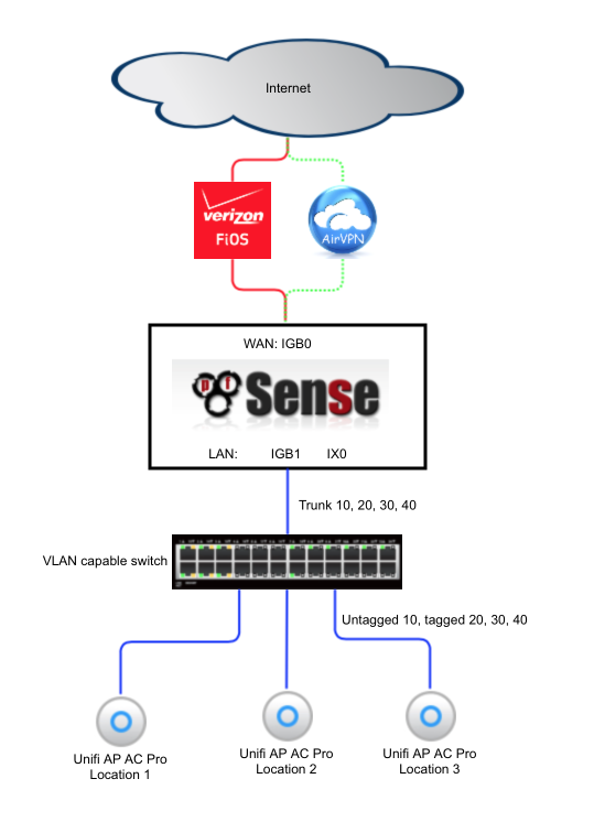
Network Topology
The following diagram illustrates the basic network topology of my network.
I had my Verizon ONT converted from the original coaxial cable to a Cat5 cable by Verizon which allowed me to connect my pfSense box directly to Verizon’s network without needing to utilise their modem for anything other than enabling some TV set top box functionality. The cost of the conversion was free if done as part of an upgrade to a 150mbps service or faster.
A VLAN capable switch is required to provide support for virtual subnets and also provides additional ports for multiple Wi-Fi access points enabling whole home coverage. I’ve listed a few cost-effective switch options in the hardware section below.
Hardware selection
Although it is possible to build a pfSense router from pretty much any old hardware, the following are worth bearing in mind as you select hardware.
CPU
Something relatively modern to reduce power consumption.
Prefer higher clock speeds over higher core counts.
AES-NI hardware acceleration will help with OpenVPN encryption.
RAM
Preferably ECC.
Avoid over spending on fancy LEDs and super aggressive CAS timings.
8/16GB is more than adequate, even with memory intensive packages like Snort or pfBlocker.
Networking
Intel network interfaces are the preferred solution. Chelsio cards have good driver support in BSD too.
Avoiding Realtek interfaces due to numerous reliability and performance issues.
Avoid anything that connects via USB.
Storage
Prefer enterprise class SSDs for write endurance and power loss protection.
SATA 6gbps is fine, PCIe4 NVMe isn’t necessary.
Configure as a matched pair in a ZFS mirror configuration for performance and resilience to single drive failure.
SMART capabilities are beneficial to monitor for degradation.
Chassis
I rack mount my server so front facing IO is valuable
Hot swappable 2.5” drive bays beneficial for how-swap drive failures.
My systems and performance
Mesozoic period to 2014
- Miscellaneous ISP supplied modems and routers with integrated wifi
- Apple airports
2014 to 2015
- Motherboard: Intel DQ77KB
- Processor: Intel Core i3-2120 3.30GHz
- RAM: 8GB (2x4GB) DDR3 1333Mhz
- System Disk: Dual Intel 510 ElmCrest 120GB 2.5” SSD
- Case & PSU: Akasa Euler S Fanless Case
- Additional NIC: Jetway ADMPEIDLA Intel i350
- OpenVPN (single connection): ~120mbps.
2015 to 2016
- Motherboard: Supermicro A1SRM
- Processor: Intel Atom processor C2758 2.4Ghz, 8-core, 20W
- RAM: 16GB (2x8GB) DDR3 1600Mhz
- System Disk: Dual Supermicro SATA-DOM 16GB in a mirrored ZFS array
- Case & PSU: Supermicro CSE-505-203B
- Additional NIC: Chelsio T520-LL-CR
- OpenVPN (single connection): ~120mbps
2016 to 2019
- Motherboard: Supermicro X10SDV
- Processor: Intel Xeon processor D-1541 2.1Ghz, 8-core, 45W
- RAM: 16GB (2x8GB) DDR4 2400Mhz
- System Disk: Dual Samsung SM863a in a mirrored ZFS array
- Case & PSU: Supermicro CSE-505-203B
- Additional NIC: Intel X520-DA2
- OpenVPN (single connection): ~300mbps
2019 to current
- Motherboard: Supermicro X11SDV
- Processor: Intel Xeon processor D-2146NT 2.3Ghz, 8-core, Quick Assist, 80W
- RAM: 16GB (2x8GB) DDR4 2400Mhz
- System Disk: Dual Intel s3710 400GB in a mirrored ZFS array
- Case & PSU: Supermicro CSE-505-203B
- Additional NIC: Intel X710-T2L (2.5gbps to modem)
- OpenVPN (single connection): ~500mbps+
Switch
A managed switch is required to provide support for the VLANs. The following are suitable options and many are available on Ebay cheaply. Look for 802.1Q support which is the ability to apply VLAN tags to traffic.
MikroTik RB260GS available for around $40. Accompanying VLAN Config guide here
NETGEAR ProSAFE GS108E available for around $50. Accompanying VLAN Config guide here
Cisco sg300-10 available for around $130 (or slightly more with PoE capabilities). Accompanying VLAN Config guide here
If you expect to have multiple heavily used subnets you may wish to consider looking for a switch that offers a 10gigabit uplink port as this facilitates a larger trunk connection to the pfSense router and thereby corresponding higher throughput. I’ve used Cisco SG500, Juniper EX4300 and Brocade 7450 & 7650 to date with good results.
You don’t need to use multiple Wi-Fi access points, each one provides all the VLANs needed. However depending on the size of the property you are trying to provide Wi-Fi access to, additional APs may be beneficial. I’ve provided an accompanying Unifi configuration guide here
Download pfSense
Download 2.5.0 release build from here.
I used the 64bit AMD64 USB memstick installer with VGA console that I installed to a 2GB USB stick with Win32 disk Imager.
Install pfSense
Set BIOS settings to enable pfSense to install
To reduce complexity and avoid any potential compatibility issues I recommend disabling unneeded features such as on-board RAID controllers and HBA controllers within the BIOS. I disable hyperthreading as it can introduce some slight but avoidable additional latency.
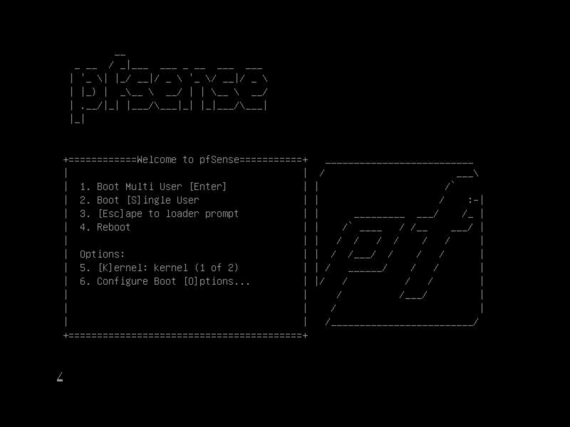
Boot
Insert the USB stick in an available USB port and boot the system from the USB stick. You may need the boot options (F11) or use the Boot menu in the BIOS to set device priority appropriately. This menu will time out after a few seconds and select option 1 on your behalf.
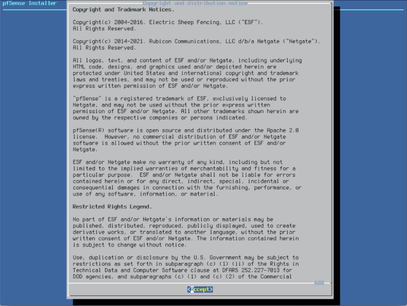
EULA
Assuming you are in agreement with the copyright and distribution notice, select Accept.
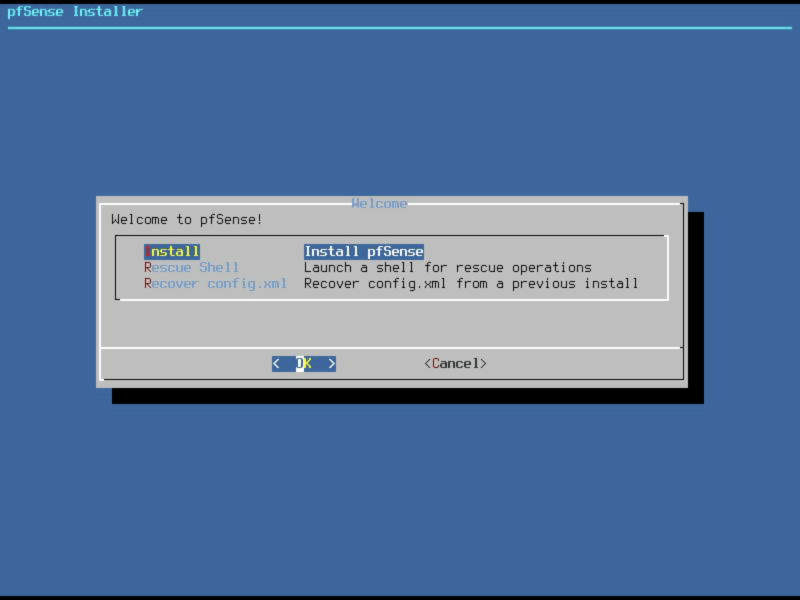
Install
You will be presented with a series of options that gives you the chance to boot to the Rescue Shell or launch the installer. As this is a fresh install, select Install.
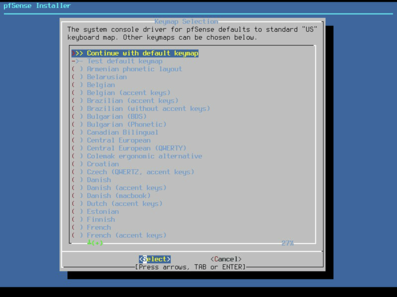
Keymap selection
Select the required keymap, I used the default keymap. Verified first with the Test default keymap option.
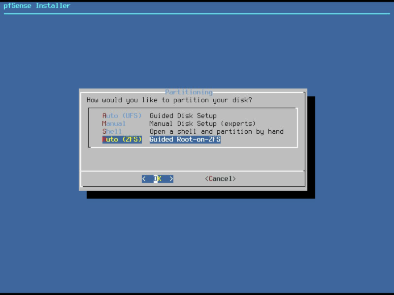
Install on ZFS partition
A change introduced with pfSense 2.4 is the option to use ZFS partitions. Using a mirrored pair of SSD’s for this install provides data redundancy in case of a single drive failure. This should not be considered a backup and is not a replacement for a proper backup strategy for your pfSense configuration.
Select the Auto (ZFS) option.
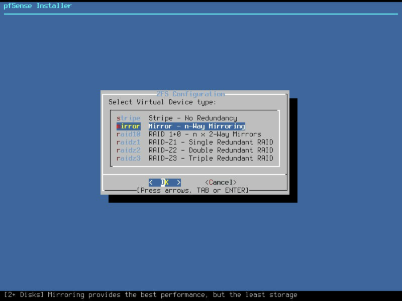
…change the ZFS Pool type to Mirrored.
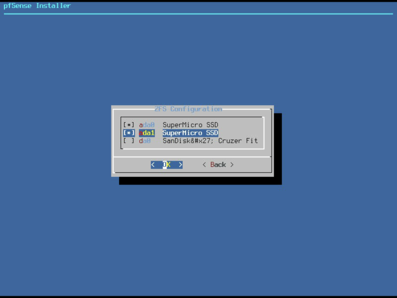
Select the pair of disk drives you wish to use for this install, I’ve selected ada0 and ada1 here as indicated by the * next to them.
Verify your settings are correct, and if so, select proceed.
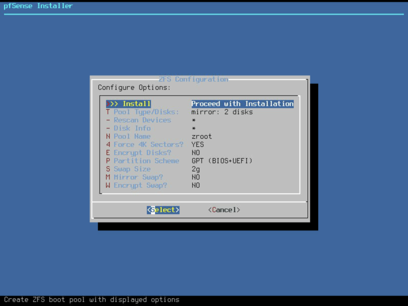
Note: If you decide to encrypt your volume, please make sure to remember the password as it is unrecoverable. Also worth noting is that the system will not boot until you enter this password at power on so think about the implications of that too before enabling.
It’s possible to configure regular scrubs of these disks to ensure reliable long-term operation and email notifications should the ZFS array develop any health issues during use.
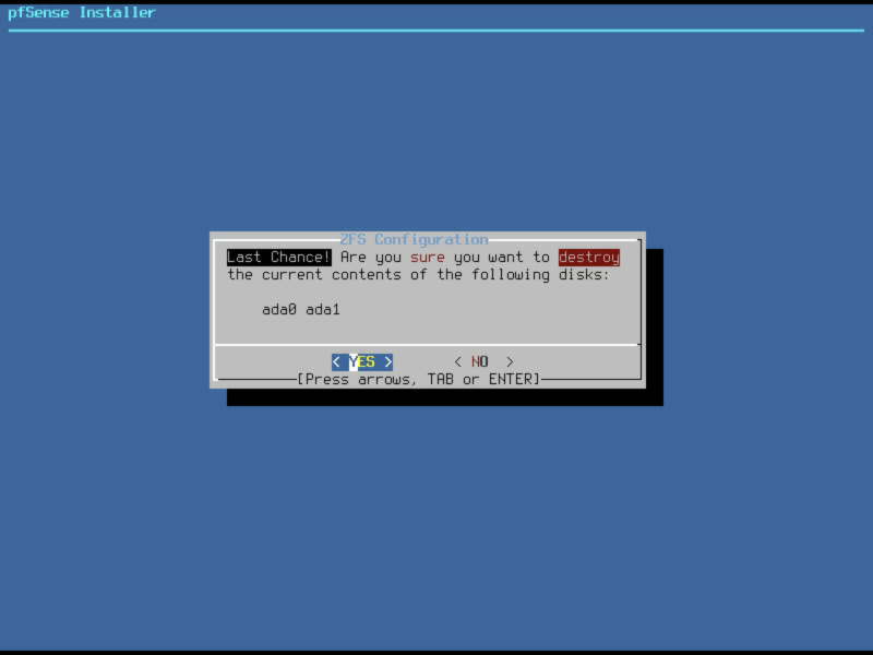
Final confirmation
Final confirmation prior to clearing the contents of the disks you selected. Select YES.
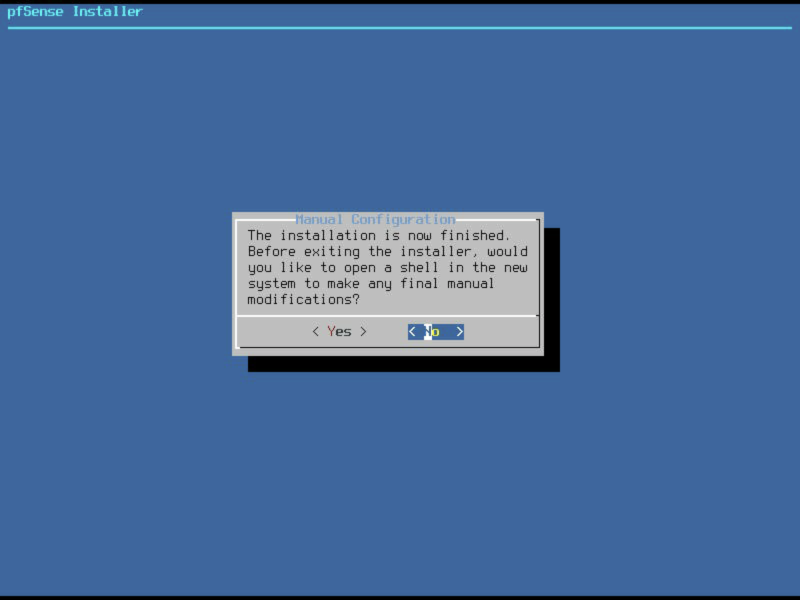
Installation
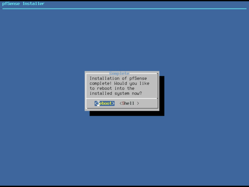
Installation will take a short while. Once installation has finished you will be prompted to make any final manual adjustments, select ‘no’.
And then select Reboot.
Initial setup
Your pfSense machine should now proceed to boot from the fresh install. After a short while you should see an option page which looks something like this.
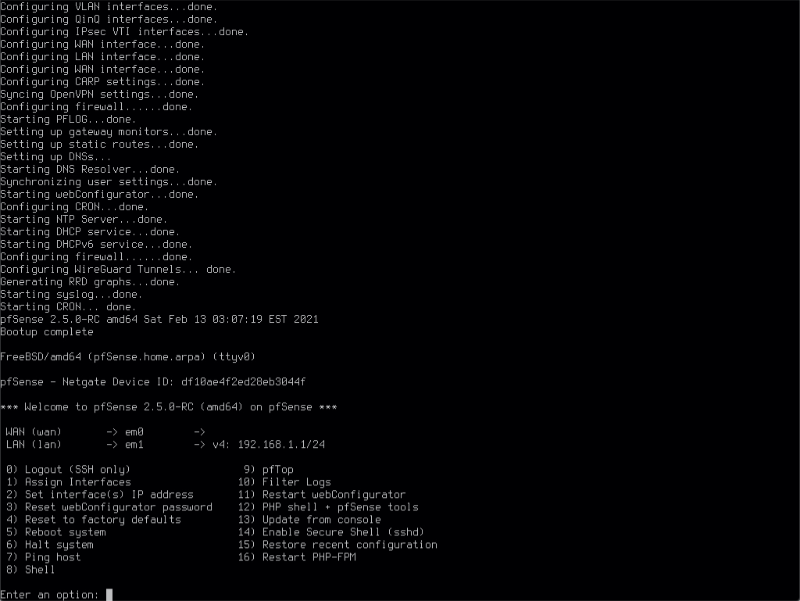
By default the installer configures the first hardware NIC as the WAN port obtaining an address via DHCP from your modem. The second NIC will be configured as your local LAN interface at 192.168.1.1. I usually leave my WAN connection modem disconnected until I’ve finished configuration. There’s a DHCP server running on the LAN interface so if you connect your PC to this port, you should be able to obtain an IP address which will allow you to access the pfSense web configurator to continue the configuration process.
login
Open a browser and enter http://192.168.1.1 into the address bar. You should be presented with a login screen as shown below. If this doesn’t work, validate the IP address space your PC is using is in the same subnet as pfSense’s local interface.
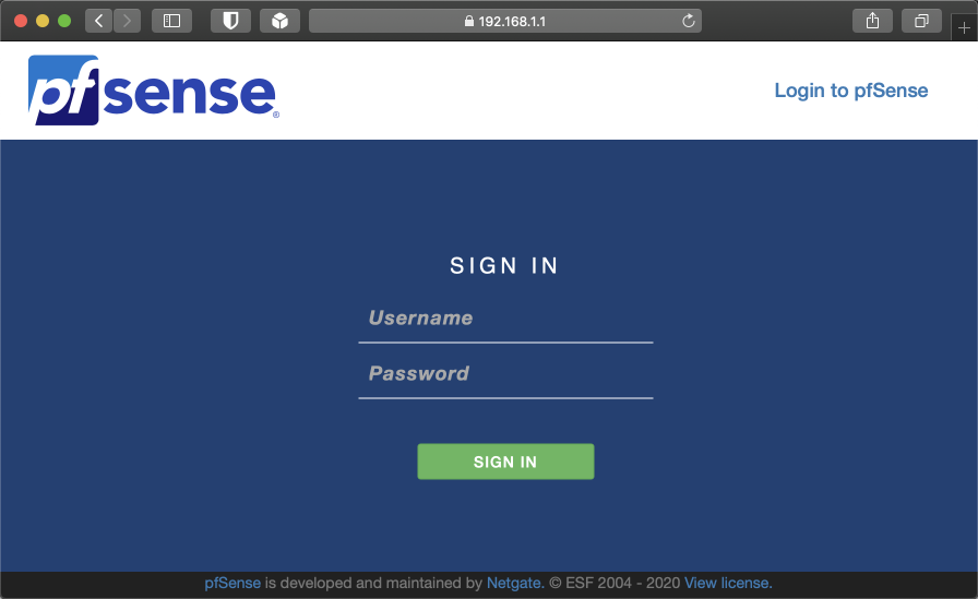
To login, enter the default username ‘admin’ and the password ‘pfsense’.
After you log in you will notice at the top of the screen a warning advising that the admin password is currently set to the default value. It’s fine to ignore this for now as you will be prompted to change it during the initial configuration.

Wizard setup
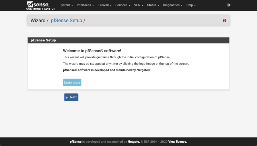
The configuration wizard will guide you through the initial configuration steps.
Select next to begin.
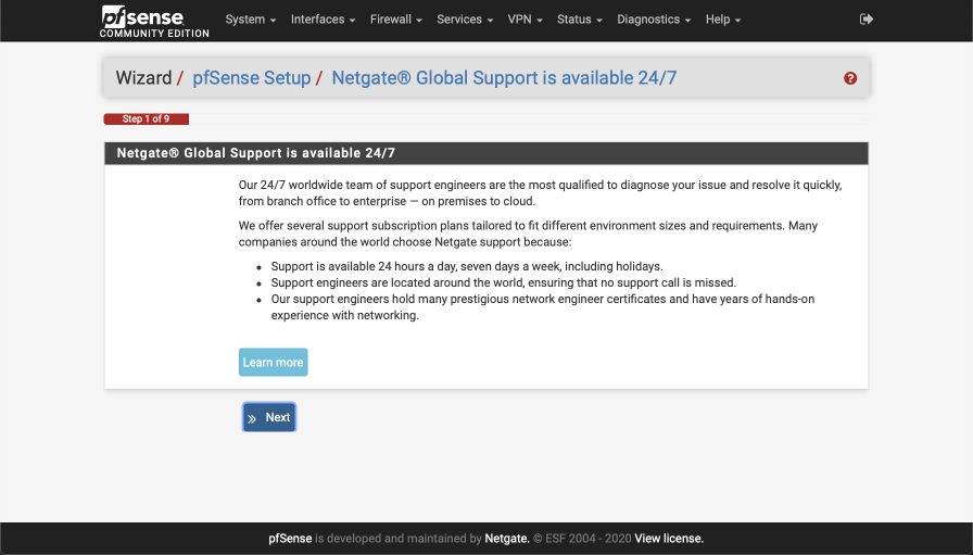
Bling your pfSense with pfSense gold
You’ll be offered the chance to purchase a pfSense gold subscription that offers support benefits.
Select ‘next’ to continue.
General Information
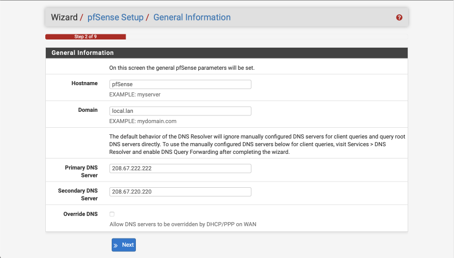
Configure this screen as specified below. We’ll use the OpenDNS servers for initial DNS resolution.
- Hostname: pfSense
- Domain: local.lan
- Primary DNS server: 208.67.222.222
- Secondary DNS server: 208.67.220.220
- Override DNS:
- Select Next
Configure NTP
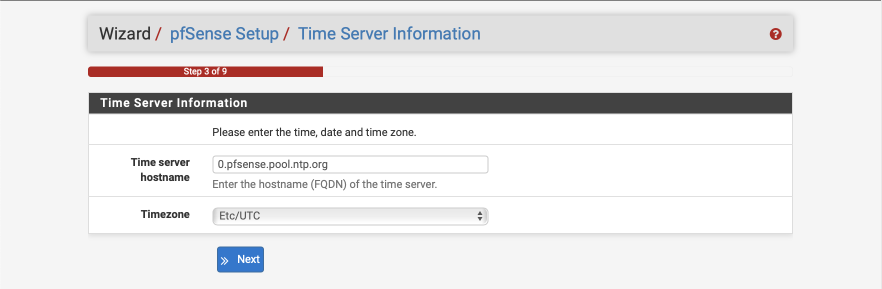
The default Time server hostname is usually correctly specified but make sure to set the Timezone to your own specific location.
- Time server hostname: 0.pfsense.pool.ntp.org
- Timezone: your local timezone
- Select Next
Configure WAN Interface
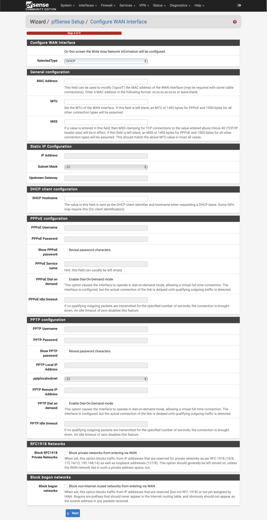
Configure this page as follows. Most of these options will remain as default, i.e empty.
Configure WAN Interface
- Selected Type: DHCP
General Configuration
- MAC Address: Empty
- MTU: Empty
- MSS: Empty
Static IP Address
- IP Address: Empty
- Subnet Mask: Default (32 displayed)
- Upstream Gateway: Empty
DHCP client configuration
- DHCP hostname: Empty
PPPoE configuration
- PPoE username: Empty
- PPPoE Password: Empty
- Show PPPoE password: Empty
- PPoE service name: Empty
- PPPoE dial on demand: unticked
- PPPoE idle timeout: Empty
PPTP configuration
- PPTP username: Empty
- PPTP password: Empty
- Show PPTP password: Empty
- PPTP local IP address: Empty
- PPTP local subnet: 32
- PPTP remote IP address: Empty
- PPTP dial on demand: unticked
- PPTP idle timeout: Empty
RFC1918 networks
- Block RFC1918 Private networks:
Block BOGON networks
- Block bogon networks:
Select next to continue.
Configure LAN Interface
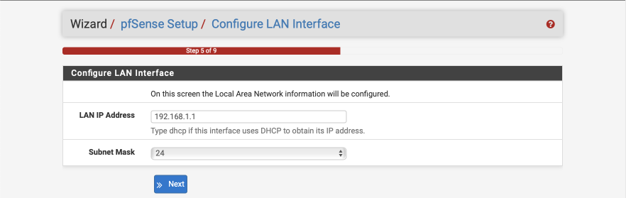
You can give your LAN interface a specific address here if needed. Leave it as 192.168.1.1 for now.
- LAN IP address: 192.168.1.1
- Subnet mask: 24
Select Next to continue.
Set Admin WebGUI Password
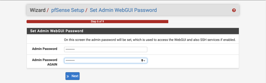
Select a strong password to protect unauthorised access to the web interface.
- Admin Password: a strong password
- Admin password again: a strong password again
Select Next to continue.
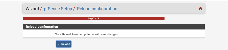
Reload to apply changes
Click Reload to reload the web configurator.
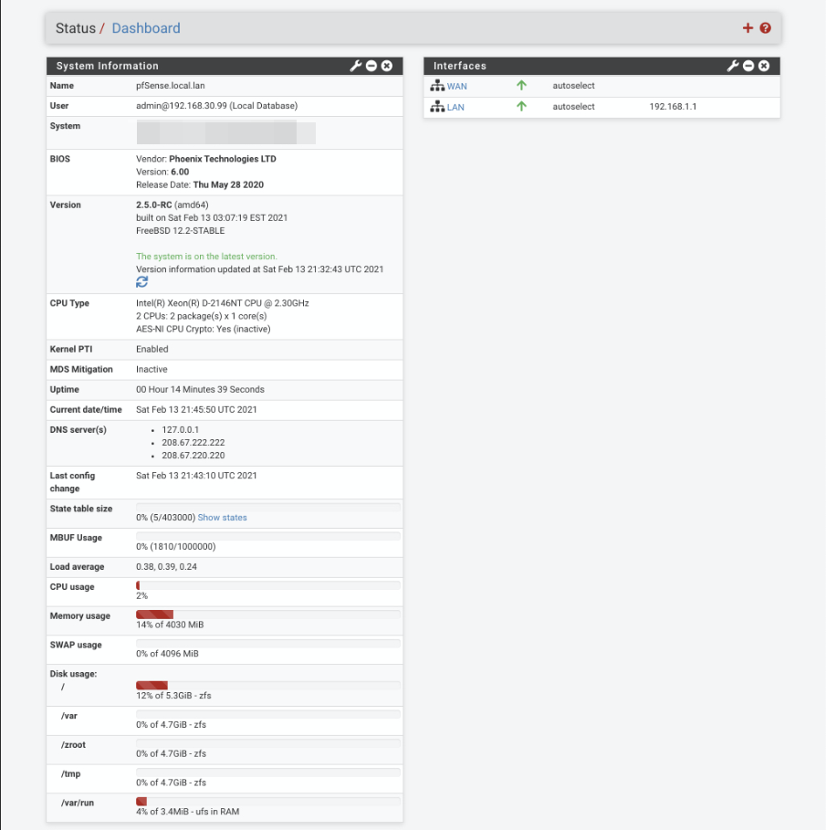
Enter the dashboard…
Consider taking the anonymous survey to help the good folks at Netgate.
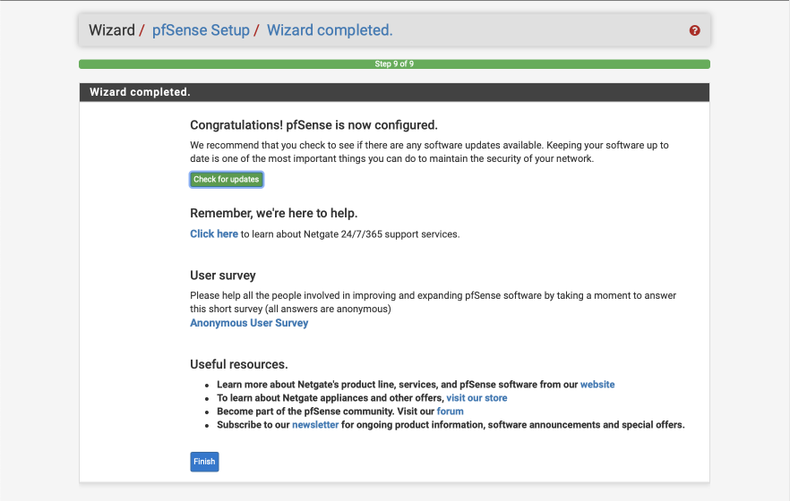
Click ‘Finish’ to enter pfSense webConfigurator where you will be presented with the main dashboard and where you will configure the rest of the system from.
pfSense configuration
We will set up some general configuration options first, using the menu bar at the top of the page.
Navigate to System > General Setup
DNS Server Settings
Enabling the forwarder to be used as a server for the firewall enables pfSense to perform reverse lookups to resolve IP addresses into device names in the firewall logs.
- DNS Server Override: Allow DNS Server list to be overridden by DHCP on WAN:
- DNS Resolution Behaviour: Use local DNS (127.0.0.1), fall back to remote DNS Servers (Default)
Click Save
Navigate to System > Advanced > Admin Access
Web Configurator
In a previous version of this guide I reallocated the web configurator to port 445, but there’s little benefit to security via this trivial obscurity. I now prefer to leave the configurator access as default on HTTPS/443 and secure it with a strong password. There are some other options to configure here though.
- WebGUI redirect, Disable webConfigurator redirect:
- WebGUI login autocomplete, Enable webConfigurator login:
- Anti-lockout: Disable webConfigurator anti-lockout rule
We can disable the systems default anti-lockout rule as we will be creating our own during the firewall setup later on.
Secure Shell
Enable SSH access to pfSense which we will make use of later.
- Enable Secure Shell:
- SSH key Only: Public Key Only
- Allow Agent Forwarding:
- SSH port: 22
- Click Save.
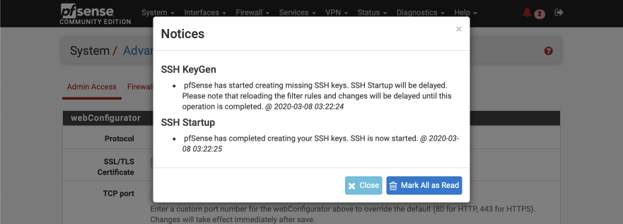
The webConfigurator will reload and the banner will display a red warning sign indicating pfSense has created SSH keys. Click on ‘Mark all as read’ to remove the warning.
Firewall/NAT configuration
Navigate to System > Advanced > Firewall/NAT
Firewall Advanced
- Firewall Optimisation options: Conservative. Tries to avoid dropping legitimate idle connections at expense of memory and CPU utilisation.
- Firewall Maximum States: 1632000 (default)
- Firewall maximum table entries: 2000000 (increased from default)
Bogon Networks
- Update Frequency: Monthly
- Click Save
Networking
Navigate to System > Advanced > Networking
IPv6 Options
Allow IPv6:
Network Interfaces
Hardware Checksum Offloading (Disable):
Higher-level checksums are traditionally calculated by the protocol implementation and the completed packet is then handed over to the hardware. Recent network hardware can perform the IP checksum calculation, also known as checksum offloading. The Ethernet hardware calculates the Ethernet CRC32 checksum and the receive engine validates this checksum. If the received checksum is wrong pfSense normally won’t see the packet, as the Ethernet hardware internally disguards the packet. IP checksum offloading can provide a modest performance improvement.
Disable Hardware TCP Segmentation Offload:
Works by queuing large buffers and letting the network interface card (NIC) split them into separate packets just before transmit. TSO should not be used on machines acting as routers.
Disable Hardware Large Receive Offload (Disable):
LRO works by aggregating multiple incoming packets from a single stream into a larger buffer before they are passed higher up the networking stack, thus reducing the number of packets to be processed. LRO should not be used on machines acting as routers as it breaks the end-to-end principle and can significantly impact performance.
hn ALTQ support:
Leave as default. The ‘hn’ driver is related to Hyper-V.
Suppress ARP handling:
Reset All States:
Miscellaneous configuration
Navigate to System > Advanced > Miscellaneous
Power Savings
- Use PowerD
- on AC: HiAdaptive
- on Battery: HiAdaptive
- unknown Power: HiAdaptive
Cryptographic Hardware Acceleration
Assuming you are using a EAS-NI enabled Intel processor select the following options. You will need to adjust according to your hardware capabilities if you are not using such a processor.
- Cryptographic Hardware: AES-NI and BSD Crypto Device (aesni, cryptodev)
- Thermal Sensors: Intel Core CPU on-die thermal sensor
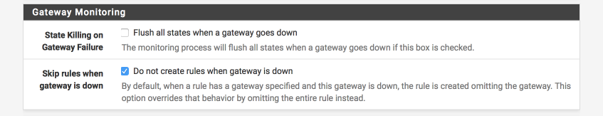
Gateway monitoring
These are important settings to reduce the chance of leaks in the event the VPN goes down for any reason.
- State Killing on Gateway Failure =
- Skip rules when gateway is down =
Click Save
Interface creation and configuration
Create VLANs
We need to identify a parent interface before we can start configuring and assigning VLANs. The parent interface refers to the physical interface that will transfer the VLAN tagged traffic.
Historically the best practice was to leave the parent interface unassigned due to undefined, unpredictable or inconsistent behaviour by some hardware, depending on the manufacturer. There was a chance that tagged traffic could be stripped of its tags and end up allocated to the parent interface introducing a security risk.
Navigate to Interfaces > Assignments and select VLANs
Create Management VLAN
Click ‘+’
Parent Interface: Your preferred parent interface, in my case, em2
VLAN Tag: 10
VLAN Priority: 0
Description: VL10_MGMT
Save
Create VPN LAN Interface
Click ‘+”
Parent Interface: Your preferred parent interface
VLAN Tag: 20
VLAN Priority: 0
Description: VL20_VPN
Save
Create CLEARNET LAN Interface
Click ‘+”
Parent Interface: Your preferred parent interface
VLAN Tag: 30
VLAN Priority: 0
Description: VL30_CLRNET
Save
Create Guest VLAN
Click ‘+”
Parent Interface: Your preferred parent interface
VLAN Tag: 40
VLAN Priority: 0
Description: VL40_GUEST
Save
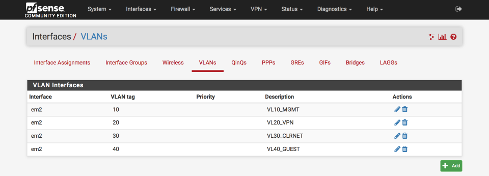
Once complete your VLAN Interfaces should look like this
Create Interfaces
Create an interface per VLAN.
Navigate to Interfaces > Assignments
Select ‘VLAN10 on em2’ from the available network ports
Click ‘Add’
Select ‘VLAN20 on em2’ from the available network ports
Click ‘Add’
Select ‘VLAN30 on em2’ from the available network ports
Click ‘Add’
Select ‘VLAN40 on em2’ from the available network ports
Click ‘Add’
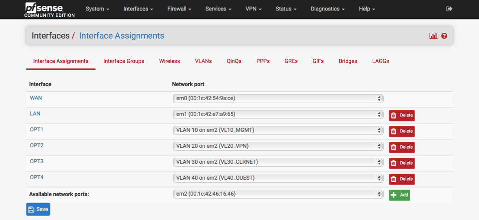
Your interface page should now look something like this, notice the parent interface (in my example, em2) remains unassigned.
Configure interface IP addresses
I match the third octet of my IP address to the VLAN ID as this makes remembering which is which easier, so VLAN id 10 = 192.168.10.0
VL10_MGMT Interface
Navigate to Interfaces > Assignments
Click on the label next to ‘VLAN10_MGMT’, its likely to be ‘OPT1’
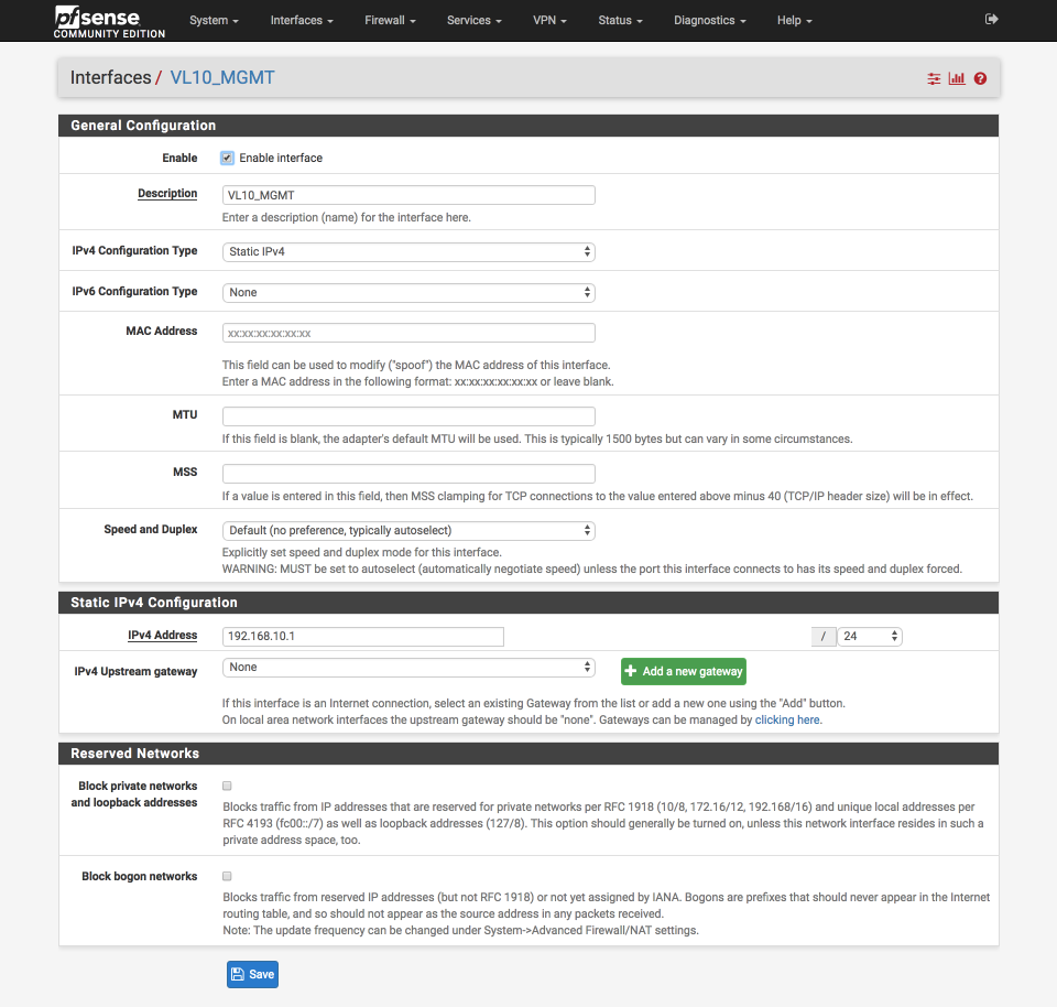
Configure this interface as follows:-
General Configuration
- Enabled =
- Description = VL10_MGMT
- IPv4 = Static IPv4
- IPv6 = None
- Mac address = None
- MTU = None
- MSS = None
- Speed & duplex = standard
Static IPv4 configuration
- IPv4 Address = 192.168.10.1/24
- IPv4 Upstream gateway = None
Private Networks
- Block private networks =
- Block bogon networks =
Verify your settings against the image below and Click Save & Apply changes.
VL20_VPN Interface
Navigate back to Interfaces > Assign and configure the VL20_VPN interface by clicking on the label next to the VL20_VPN network port. We’ll configure this similarly to the VL10_MGMT Interface except we’ll give it a unique name and IP address.
General Configuration
- Enabled =
- Description = VL20_VPN
Static IPv4 configuration
- IPv4 Address = 192.168.20.1/24
Click Save & Apply changes.
VL30_CLRNET Interface
Navigate back to Interfaces > Assign and configure the VL30_CLRNET interface by clicking on the label next to the VL30_CLRNET network port. We’ll configure this similarly to the VL10_MGMT Interface except we’ll give it a unique name and IP address.
General Configuration
- Enabled =
- Description = VL30_CLRNET
Static IPv4 configuration
- IPv4 Address = 192.168.30.1/24
Click Save & Apply changes.
VL40_GUEST Interface
Navigate back to Interfaces > Assign and configure the VL40_GUEST interface by clicking on the label next to the VL40_GUEST network port. We’ll configure this similarly to the VL10_MGMT Interface except we’ll give it a unique name and IP address.
General Configuration
- Enabled =
- Description = VL40_GUEST
Static IPv4 configuration
- IPv4 Address = 192.168.40.1/24
Click Save & Apply changes.
Configure interface DHCP
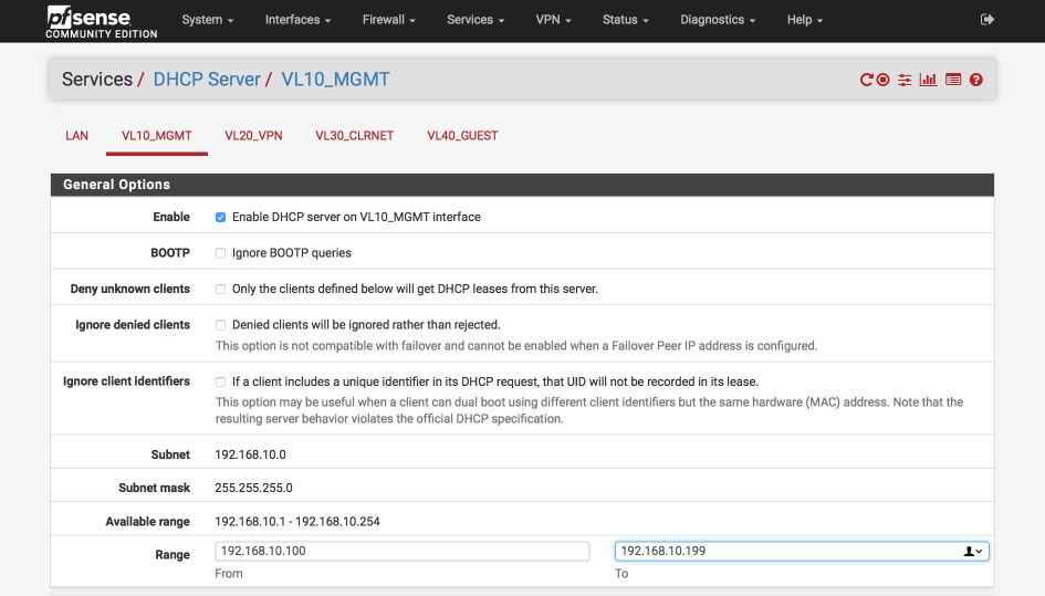
I like to set each interface to use x.x.x.100-199 for dynamic addresses and reserve x.x.x.10-99 for static allocations. Depending on the number of devices in your network you may need to adjust this to suit your needs.
Navigate to Services > DHCP Server
Select VL10_MGMT tab and set the DHCP server as follows:-
- Enabled =
- Range
- From : 192.168.10.100
- To : 192.168.10.199
Verify your settings against the image below (I only display the general options below as the rest are default) and then click Save & Apply
Now we’ll set up the rest of the interfaces. Select VL20_VPN tab and set the DHCP server as follows:
- Enabled =
- Range
- From : 192.168.20.100
- To : 192.168.20.199 - Save & Apply
Select VL30_CLRNET tab and set the DHCP server as below.
- Enabled =
- Range
- From : 192.168.30.100
- To : 192.168.30.199 - Save & Apply
Select VL40_GUEST tab and set the DHCP server as below. For my guest network you can use your ISP DNS servers or those from a public provider such as Cloudflare which I’ve use here.
- Enabled =
- Range
- From : 192.168.40.100
- To : 192.168.40.199 - DNS Server 1 : 1.1.1.1
- DNS Server 2 : 1.0.0.1
- Save & Apply
Create and configure the VPN client
Generate AirVPN certificates
Now we’ll generate our required AirVPN certificates. Open a browser and go to airvpn.org, sign into your account and then navigate to Client Area > Config Generator.
Its worth spending some time reviewing the statistics of the potential servers you are considering connecting to before finalising your selection. Click on the server name to see statistics on numbers of users, traffic and latency as well as any historic connectivity issues. I specify individual servers in my connections by IP address as this reduces any chance of DNS poisoning. The IP addresses are generally stable and seldom change in my experience.
- Advanced Mode:
- Operating System: Router
- IP layer exit: IPv4
- Connect with IP layer: IPv4
- Advanced
- Bundled Executables: No
- Resolved hosts:
- Filename Prefix: blank
- Bundled Executables: No
- Advanced - OpenVPN only
- OpenVPN version: >= 2.5
- Data Cipher: Automatic
- Separate keys/certs from .ovpn file
- OpenVPN custom directives: blank, we will confgiure these directly in pfSense later.
- Protocol:
- Type: OpenVPN
- Protocol: UDP
- Port: 443
- Specs: tls-crypt, tls 1.2 (please double check you select an appropriate ‘tls-crypt, tls1.2’ end point. This is a common source of problems.)
- Servers: Your preferred Country or Single Server. I prefer to use a single server
- Click [Generate]
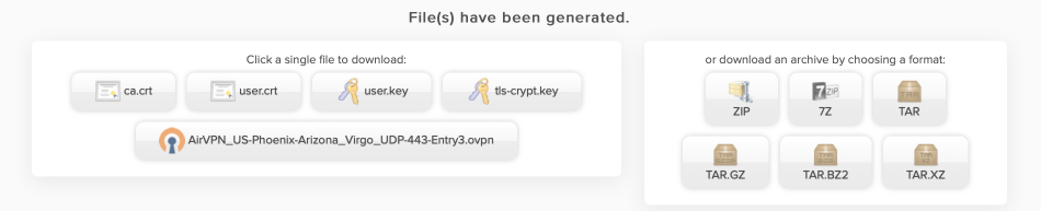
Download the certificates to your local machine. Either download one of the packed archives and extract, or download the separate files. You will use these 4 certificates and the .ovpn config file to configure the OpenVPN client in pfSense in the next step.
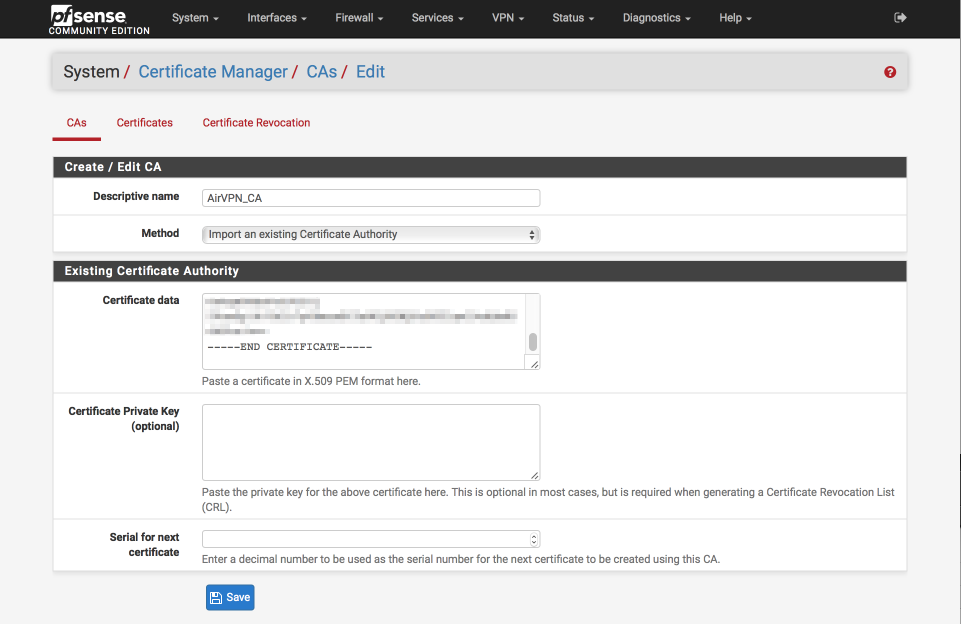
Back in pfSense’s GUI, create and configure the Certificate Authority.
Navigate to System > Cert Manager > CAs
- Click ‘+’
- Descriptive Name = AirVPN_CA
- Method = Import an existing Certificate Authority
- Certificate data = Paste the contents of ca.crt file in here
- Certificate Private Key (optional) = blank
- Serial for next certificate = blank
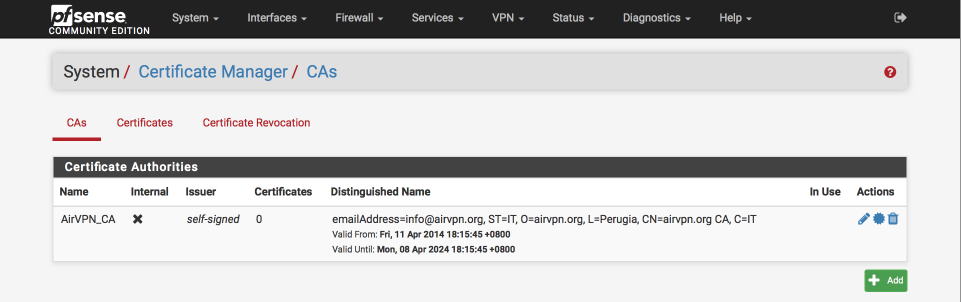
- Click Save
This is what the certificate authority should look like once you’ve added it
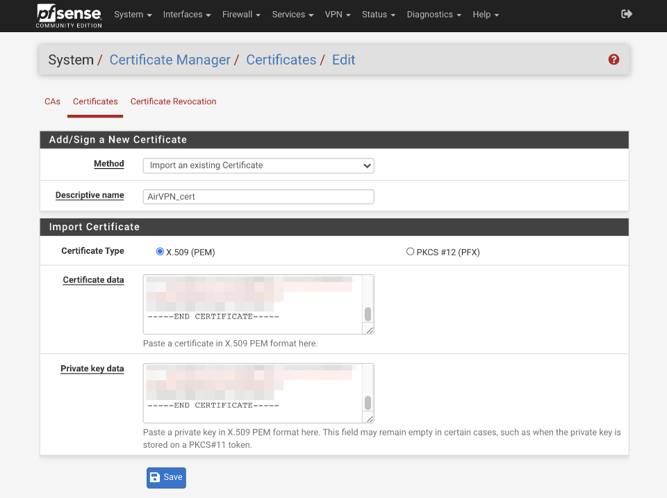
Import AirVPN certificate.
Navigate to System > Cert Manager and select certificates
- Click ‘+ Add/Sign’
- Method = Import existing cert
- Descriptive Name = AirVPN_cert
- Certificate type = X.509 (PEM)
- Certificate data = paste the contents of user.crt here
- Private key data = paste the contents of user.key here
- Click Save
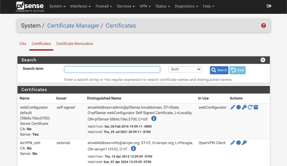
This is what the certificate authority page should look like once you’ve added it
Create VPN client
At the time of the latest revision of this guide AirVPN has updated their infrastructure to OpenVPN 2.5 and supports both AES-GCM and CHACHA20-POLY1305 TLS ciphers.
TLS mode is the most powerful crypto mode of OpenVPN, both for security and for flexibility. TLS mode works by establishing control and data channels that are multiplexed over a single TCP/UDP port. The OpenVPN client initiates a TLS session over the control channel and uses it to exchange cipher and HMAC keys to protect the data channel. TLS mode uses a robust reliability layer over the UDP connection for all control channel communication, while the data channel, over which encrypted tunnel data passes, is forwarded without any mediation. The result is the best of both worlds: a fast data channel that forwards over UDP with only the overhead of encrypt, decrypt, and HMAC functions, and a control channel that provides all of the security features of TLS, including certificate-based authentication and Diffie Hellman forward secrecy.
From the AirVPN server status pages we can learn what version of OpenVPN server is running and what ciphers are supported, for example, in the case of Hercules the following are supported
- Control Channel:
TLS-DHE-RSA-WITH-CHACHA20-POLY1305-SHA256 TLS-DHE-RSA-WITH-AES-256-GCM-SHA384 TLS-DHE-RSA-WITH-AES-256-CBC-SHA256 TLS-DHE-RSA-WITH-AES-256-CBC-SHA - Data Channel:
CHACHA20-POLY1305 AES-256-GCM AES-256-CBC AES-192-GCM AES-192-CBC AES-128-GCM AES-128-CBC
Cipher definition
Control channel cipher is specified as TLS_DHE_RSA_WITH_AES_256_GCM_SHA384, where
protocol: TLS
key exchange algorithm: DHE. How keys will be exchanged by the client and the server.
authentication: RSA. Digital signature that shows the type of certificate and verifies the SSL is legitimate.
session cipher: AES Session cipher
session encryption key size (bits): 256 Session encrpytion bitsize
session encrpytion type: GCM Session encrpytion type
hash function: SHA Hashing algorithm that both authenticates messages and ensures data integrity
digest size (bits): 384 Hashing algorithm bitsize
Cipher preference
It is important to understand this information as the order of preference for cipher selection is defined by the server, not the client. This guide configures the client to negotiate AES-256-GCM and fall back to AES-256-CBC if not possible. If you wish to use a less secure but more performant cipher such as AES-GCM-128, you will need to specify that in both the Allowed Data Encrpytion Algorithm AND the Fallback Data Encryption Algorithm options due to the position of AES-256-CBC in the server side cipher ordering.
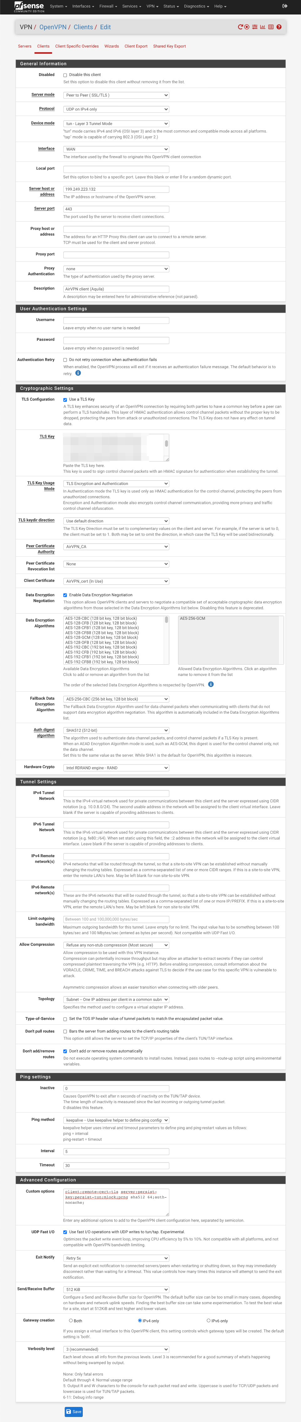
Client configuration
Navigate to VPN > OpenVPN and select Clients
- Click ‘+ Add’
General Information
- Disabled =
- Server Mode = Peer to Peer (SSL/TLS)
- Protocol = UDP on IPv4 only
- Device mode = tun - Layer 3 Tunnel Mode
- Interface = WAN
- Local Port = empty
- Server host = AirVPN server address from the AirVPN .ovpn configuration file you downloaded. It’s the four numbers separated by ‘.’s after the word remote, e.g
remote 199.249.223.132 443The first four numbers are the IP address, and the last number is the port number. - Server port = Change this from default OpenVPN port of 1194 to 443 (or the second number from the remote line in the .ovpn configuration file)
- Proxy host or address = empty
- Proxy Port = empty
- Proxy authentication = none
- Description = AirVPN client
User Authentication Settings
- Username = Empty
- Password = Empty
- Authentication Retry =
Cryptographic settings
- TLS Configuration = Use a TLS Key =
- Automatically generate a TLS Key =
- TLS Key = Paste contents of the ta.key/tls-crypt.key downloaded here
- TLS Key Usage Mode = TLS Encryption and Authentication
- TLS keydir direction = use default direction
- Peer certificate authority = AirVPN_CA
- Peer certificate revocation list = None
- Client certificate = AirVPN_cert (CA: AirVPN_CA)
- Data Encryption Negotiation =
- Allowed Data Encryption Algorithms = AES-256-GCM
- Fallback Data Encryption Algorithm = AES-256-CBC
- Auth digest Algorithm = SHA512 (512-bit)
- Hardware crypto = Intel RDRAND (assuming you have an Intel processor)
Tunnel Settings
- IPv4 Tunnel Network = Empty
- IPv6 Tunnel Network = Empty
- IPv4 Remote Network(s) = Empty
- IPv6 Remote Network(s) = Empty
- Limit outgoing bandwidth = Default
- Allow Compression = Refuse any non-stub compression (Most Secure)
- Topology = Subnet - One IP address per client in a common subnet
- Type-of-Service =
- Dont pull routes =
- Dont add/remove routes =
Ping Setting
- Inactive = 0
- Ping method = keepalive
- Interval = 5
- Timeout = 30
Advanced Configuration
- Custom Options =
client; persist-key; persist-tun; remote-cert-tls server; prng sha256 64; mlock; auth-nocache;
I’ve provided a brief summary of each of these parameters below. A more complete description can be found in the OpenVPN manual.
client: Specifies this is a client configuration.
persist-key: Don’t re-read key files across OpenVPN client restarts.
persist-tun: Don’t close and reopen TUN/TAP device across OpenVPN client restarts.
remote-cert-tls server: Security option for clients to ensure that the host they connect to is a designated server.
prng sha256 64: Security option to increase Pseudo-Random Number Generator nonce secret length.
mlock: Security option to disables paging to ensures that key material and tunnel data are never written to disk due to virtual memory paging operations.
auth-nocache: Security option to prevent caching username/passwords in virtual memory.
- UDP Fast I/O =
- Exit notify = Retry 5x
- Send/Receive Buffer = 512KiB (tweak depending on available RAM and performance testing)
Gateway Creation = IPv4 - Verbosity = 3 (Recommended) (adjust as needed for debugging / production use etc)
- Click Save
Create OpenVPN interface
We’ll now assign the OpenVPN interface we just created to a pfSense interface. This will enable us to configure the interface by
- enabling firewall tab under Firewall > Rules
- adding reply-to rules on VPN interface for return routing
- adding gateway for policy routing
- enabling the VPN interface to be selected elsewhere in the pfSense interface
- providing more configuration for port forwards and outbound NAT rules
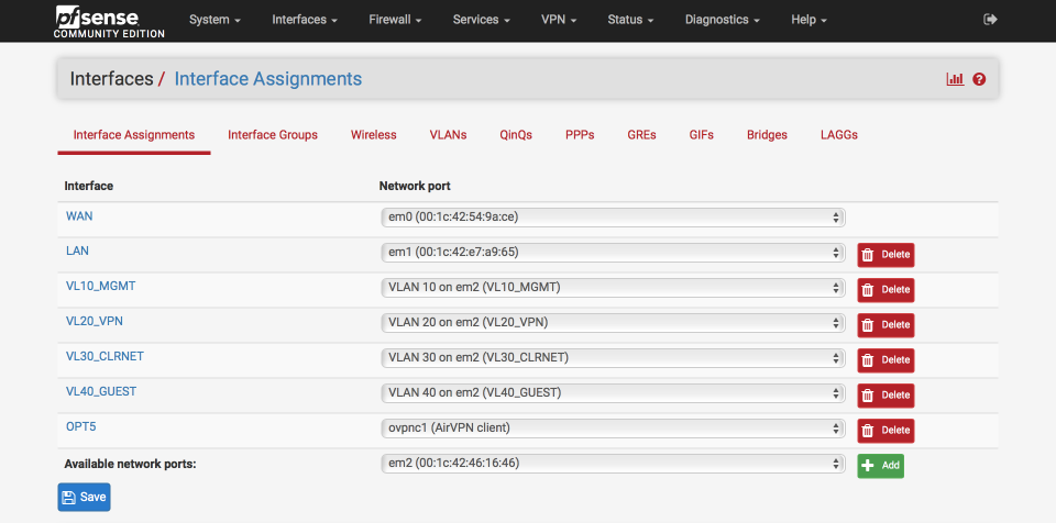
Navigate to Interfaces > Assignments
- Available network ports: Select ‘ovpnc1 (AirVPN client)`
- Click ‘+’ at the bottom right which will add a new OPTx interface.
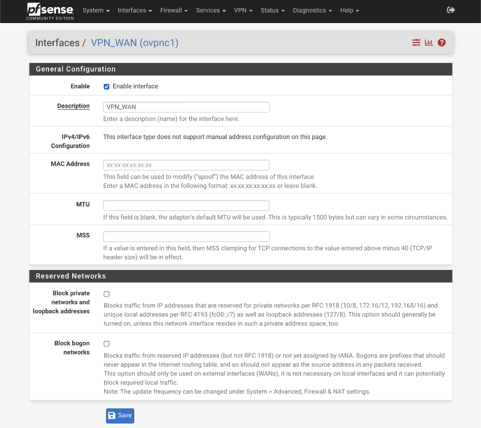
- Click on the new OPTx interface name (OPT5 in my example below).
Set up the interface as follows:
- Enable Interface =
- Description = VPN_WAN
- MAC Address = blank (xx:xx:xx:xx:xx)
- MTU = blank
- MSS = blank
- Block private networks =
- Block bogon networks =
- Click Save and Apply changes
Configure Gateways
Navigate to System > Routing.
It’s not possible to rename the auto-generated default gateway ‘VPN_WAN_VPNV4’ to a more succinct ‘VPN_WAN’. We can achieve the same result by creating a new gateway called VPN_WAN that will replace the default ‘VPN_WAN_VPNV4’ gateway.
We will also provide gateway monitoring via an external address, in this case Route53’s 4.2.2.1
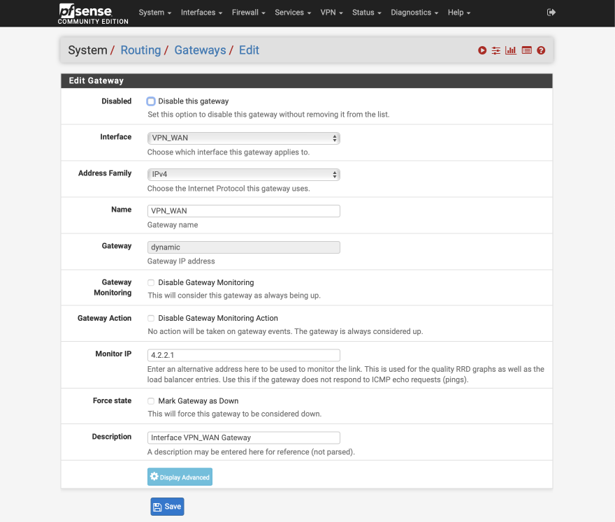
Click on ‘+Add’.
- Disabled =
- Interface = VPN_WAN
- Address family = IPv4
- Name = VPN_WAN
- Gateway = Empty
- Default Gateway =
- Disable gateway monitoring =
- Gateway Action =
- Monitor IP = 4.2.2.1
- Force state =
- Description = Interface VPN_WAN Gateway
- Click Save
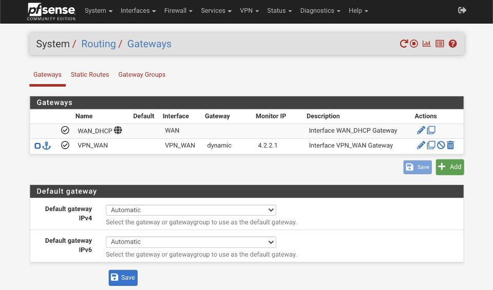
Set the default IPv4 gateway to WAN_DHCP.
After applying the new gateway configuration, the Gateway summary should look like this
Notes on VPN configuration
Performance
If you see that the CPU core which OpenVPN is running on (use Diagnostics > System Activity) is running at close to 100%, consider using a lighter cipher such as AES-128-GCM. To use AES-128-GCM remove the higher bit count algorithms from the Allowed Data Encryption Algorithm section.
If you are using a CPU without AES consider adding CHACHA20-POLY1305 to the Allowed Data Encryption Algorithm section and see if that helps.
Security
Compression and encryption are a tricky combination. If an attacker knows or is able to control (parts of) the plain text of packets that contain secrets, the attacker might be able to extract the secret if compression is enabled. See the CRIME and BREACH attacks on TLS which also leverage compression to break encryption. This guide is created to prioritise security over performance so compression is not enabled.
Preventing IP address leaks
These should have been configured during the initial configuration section but as these are important settings to help prevent leaks they are worth verifying.
Navigate to System > Advanced and select Miscellaneous. Scroll down to Gateway Monitoring and ensure the following options are set.
- State Killing on Gateway Failure =
- Skip rules when gateway is down =
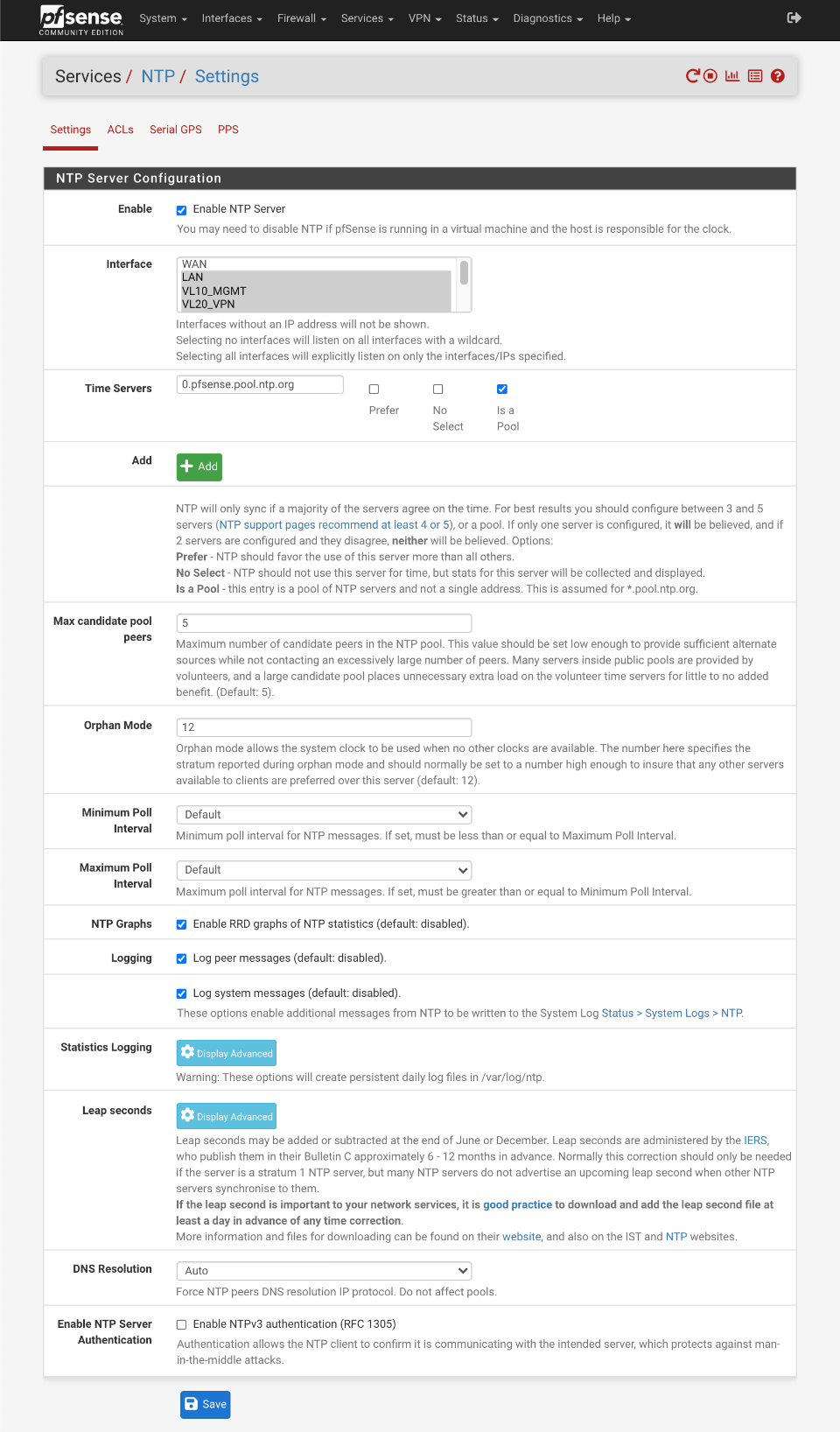
NTP Configuration
My entire network is synced to my pfSense router with the exception of devices on the guest network which are permitted to sync with external time servers too. The configuration below uses a public pool for time reference but it’s possible to reduce this external dependency by setting up a local GPS based time server. There’s a SBC local time server guide here for reference.
Navigate to Services > NTP
- Interface: LAN, VL10_MGMT, VL20_VPN, VL30_CLRNET
- Time Servers
- 0.pfsense.pool.ntp.org, Prefer , No Select , Is a Pool - Max candidate pool peers: 5 (default)
- Orphan Mode: 12
- Minimum Poll Interval: default
- Maximum Poll Interval: default
- NTP Graphs:
- Logging:
- Log peer messages:
- Log system messages: - DNS Resolution: Auto
- Enable NTP Server Authentication:
Click Save
This is how your NTP server should look.
DNS Configuration
One area I’ve received several questions on is using DNS via SSL/TLS. I’m still personally in favour of using root name resolvers via the DNS Resolver without encryption rather than forwarding SSL/TLS secured queries to public servers. My reasoning is that I would rather have unencrypted names resolved by the authoritative root name servers rather than encrypt my DNS lookups with SSL/TLS but have them resolved by a non authoritative service such as Cloudflare or OpenDNS. This assessment is influenced knowing that unencrypted queries are exposed only through my AirVPN endpoints therefore affording me anonymity. This is an area I’m still evaluating and would welcome feedback.
I make use of three sets of DNS resolvers to provide name resolution across my various local subnets.
- Cloudflare DNS: Used for guest network. I previously used my ISP’s servers on my Guest network but adding a second 4G LTE WAN interface for failover required changing to servers accessible from both my primary ISP and my 4G provider.
- DNS Forwarder: I use OpenDNS servers to resolve lookups on my clearnet network. This retains some privacy and avoids basic censorship that might be an issue with a local ISP. Local name resolution is handled by my DNS Resolver.
- DNS Resolver: I still prefer to use the DNS root nodes via the Resolver for devices connected via VPN. I’ve also configured my resolver to be authoritative for my local.lan domain which means that names not resolved as part of local.lan are not forwarded to the root notes for resolution preventing unneeded leakage of information.
In general my system is designed to
- Support multiple gateways
- Prevent as much information as possible being gathered by my ISP
- Do not leak IP address when using the VPN under any circumstance
- Enable local device lookups on all non-guest interfaces
- Support WPAD auto configuration
- Provide secure DNS lookups when connected to my secured networks by keeping DNS queries within the VPN tunnel
- Optimise local performance with DNS lookup caching
- Support DNS redirection to enable advert/tracker filtering
To support this feature set, all local devices are set to use the pfSense router as their sole DNS server using the local Resolver or Forwarder. Cached or local names found in the DNS Resolver will be returned to the client and unknown lookups will be resolved externally with either OpenDNS or the root nodes via the AirVPN tunnel. Results returned will be cached for future reference increasing time to response, and also reducing the load on non-local infrastructure.
To reduce any leaks, I lock down the Resolver to the VPN_WAN interface. If the VPN connection goes down, DNS lookups won’t be possible and this is why I provide the guest and clrnet networks as a backup on the rare occasions AirVPN goes down. It is possible to setup multiple simultaneous connections to AirVPN which provides further redundancy and is covered in this guide.
I think this is a good compromise between providing the required functionality and security. I’ve spent time verifying there are no leaks with this setup but there are no guarantees given so please do your own testing.
VL40_GUEST is not added to the interfaces selection as devices on that subnet do not utilise the DNS Resolver or Forwarder to resolve names but reference DNS servers as awarded from the VL40_GUEST DHCP server.
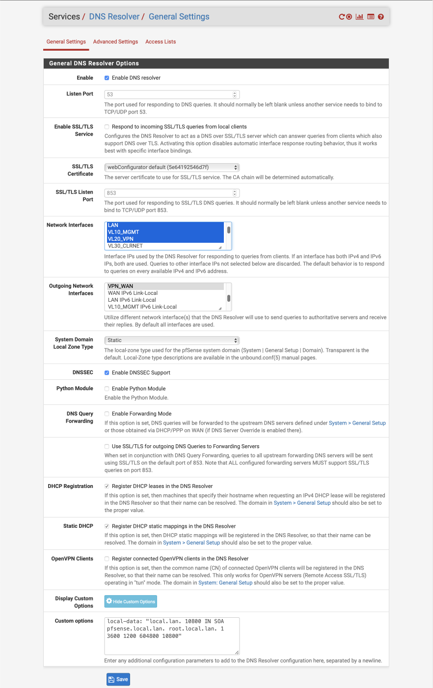
DNS Resolver
First configure the DNS Resolver, navigate to Services > DNS Resolver > General Settings
- Enable DNS Resolver =
- Listen Port = 53
- Enable SSL/TLS Service =
- SSL/TLS Certificate = webConfigurator default
- SSL/TLS Listen Port = 853 (unused)
- Network Interfaces: Select LAN, VL10_MGMT, VL20_VPN and localhost
- Outgoing Network Interfaces: Select only VPN_WAN
- System Domain Local Zone Type: Static
- DNSSEC =
- Python module =
- Python Module Order = pre validator
- Python Module Script = No Python Module Scripts Found
- DNS Query Forwarding =
- DHCP Registration =
- Static DHCP =
- OpenVPN Clients =
- Custom options =
local-data: "local.lan. 10800 IN SOA pfsense.local.lan. root.local.lan. 1 3600 1200 604800 10800" - Click Save
The custom option declares the DNS Resolver as authoritative for the .local.lan domain. The parameters relate to the following options
- ttl = 10800 (3 hours)
- primary name server = pfsense.local.lan
- responsible mail address = root.local.lan
- serial = 1
- refresh = 3600 (1 hour)
- retry = 1200 (20 mins)
- expire = 604800 (7 days)
- default TTL = 10800 (3 hours)
Navigate to Services > DNS Resolver > Advanced Settings
Advanced Privacy Options
- Hide Identity =
- Hide Version =
- Query Name Minimization =
- Strict Query Name Minimization =
Advanced Resolver Options
- Prefetch Support =
- Prefetch DNS Key Support =
- Harden DNSSEC Data =
- Serve Expired =
- Aggressive NSEC =
- Message Cache Size: 4MB
- Outgoing TCP Buffers: 10
- Incoming TCP Buffers = 10
- EDNS Buffer Size: 4096
- Number of queries per thread: 512
- Jostle timeout = 200
- Maximum TTL for RRsets and messages: 86400
- Minimum TTL for RRsets and messages: 0
- TTL for host cache entries: 15 minutes
- Number of hosts to cache: 10000
- Unwanted reply threshold: Disabled
- Log Level: 1 (adjust for debugging or production etc)
- Disable Auto-added Access control =
- Disable Auto-added Host Entries =
- Experimental Bit 0x20 Support =
- DNS64 Support =
Click Save & Apply changes
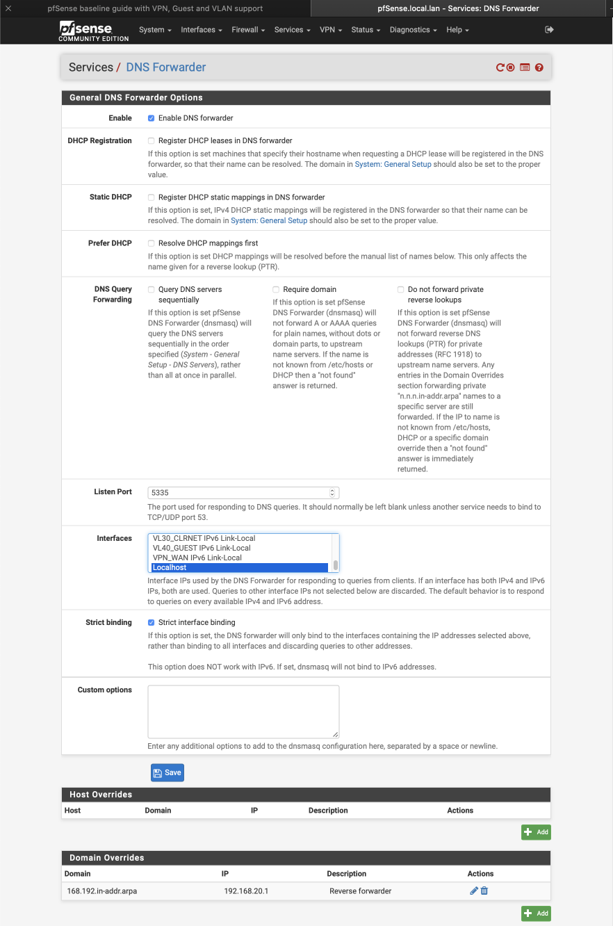
DNS Forwarder
The DNS Forwarder is used to resolve lookups from the VL30_CLRNET subnet by forwarding queries to the DNS servers specified earlier during the wizard setup. They can be be edited if necessary by navigating to System > General > Setup. The DNS Resolver we previously configured is set to use port 53 so we need to set the forwarder up to use another port. I’ve updated my guide to run this service to port 5335 to avoid any conflicts with the MDNS multicast system as this could cause some conflicts for users looking to use the Avahi package. We set the Forwarder to listen to the localhost (127.0.0.1) network and will later create a port forward to redirect traffic from clients on this subnet.
Navigate to Services > DNS Forwarder
- Enable DNS Forwarder =
- DHCP registration =
- Static DHCP =
- Prefer DHCP =
- DNS Query Forwarding:
- Query DNS servers sequentially =
- Require domain =
- Do not forward private reverse lookups =
- Listen Port = 5335
- Interfaces = localhost
- Strict binding =
- Custom options = Empty
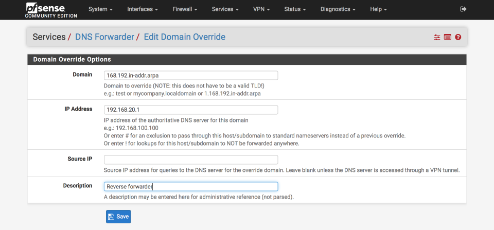
Under domain overrides, click ‘+add’ to create forwarder for local lookups
- Domain = 168.192.in-addr.arpa
- IP address = 192.168.20.1
- Source IP = Empty
- Description = Reverse forwarder
Click Save & Apply
The complete DNS Forwarder should look like this
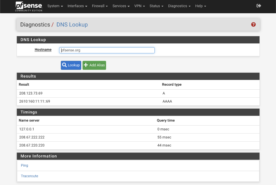
Verify DNS functionality
It’s worth verifying that basic DNS lookups work before we complicate matters by introducing the VPN DNS server.
Navigate to Diagnostics > DNS Lookup
- Enter an address to test lookups with, i.e pfsense.org
- Click DNS Lookup
You should see an IP address returned as well as the time taken to receive the response from the servers configured in the System > General setup page. Successive attempts to resolve the same address should be cached and be returned faster than the original query.
Configure NAT
NAT is needed to convert your private local IP addresses to the global registered address space. We’ll set this up for both our WAN and VPN_WAN gateways now. Specifically, we will enable functionality to allow
- All subnets to transition to the WAN address range
- VPN subnet to transition to both VPN_WAN & WAN ranges (this is needed to facilitate a SELECTIVE_ROUTING rule which will direct certain outbound VPN subnet traffic through the WAN gateway despite being on the VPN subnet).
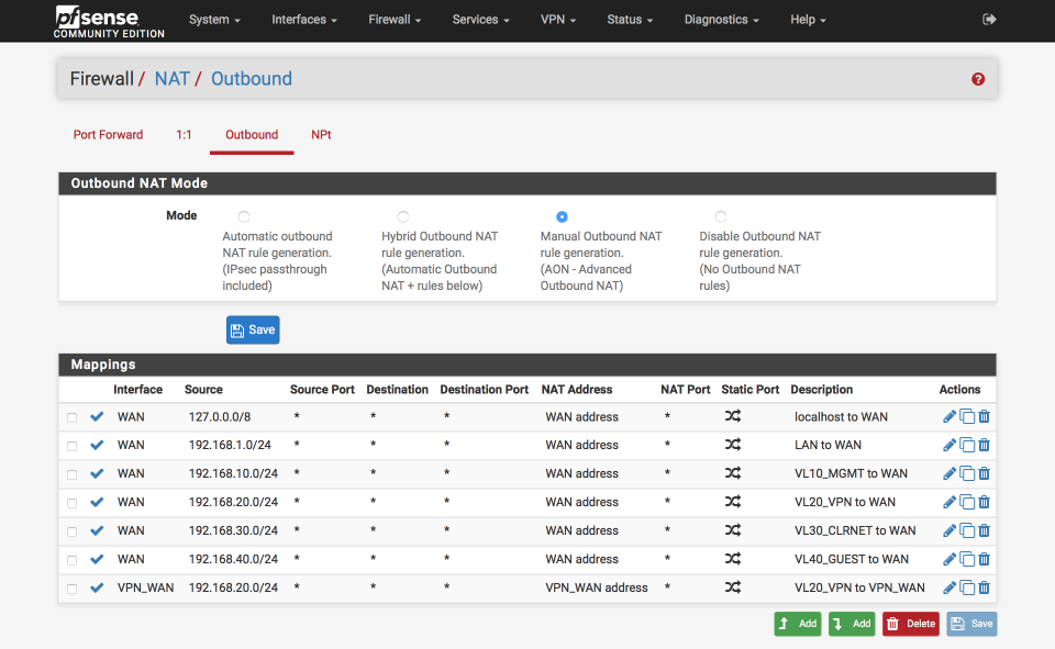
Navigate to Firewall > NAT and select Outbound
- Select ‘Manual outbound NAT rule generation`
- Click Save & Apply configuration
A number of rules will be created automatically. Delete any with ‘500’ in the Destination Port column as we won’t need these.
Edit ‘localhost to WAN’ NAT
Click the pencil icon next to 127.0.0.0 / 8 line to edit it.
Advanced Outbound NAT Entry
- Disabled =
- Do not NAT =
- Interface = WAN
- Address Family = IPv4
- Protocol = any
- Source
- Type = Network
- Address = 127.0.0.0 / 8
- Source port: Blank
- Destination
- Type = Any
- Address = Blank
- Destination Port: Blank
- Not :
Translation
- Address = Interface Address
- Port = blank
Miscellaneous
- No XMLRPC Sync =
- Description = Localhost to WAN
Click Save & Apply
Edit ‘LAN to WAN` NAT
Click the pencil icon next to auto created LAN rule line to edit it
Advanced Outbound NAT Entry
- Disabled =
- Do not NAT =
- Interface = WAN
- Address Family = IPv4
- Protocol = any
- Source
- Type = Network
- Source Network = 192.168.1.0 / 24
- Source port: Blank
- Destination
- Type = Any
- Address = Blank
- Destination Port: Blank
- Not :
Translation
- Address = Interface Address
- Port =
Miscellaneous
- No XMLRPC Sync =
- Description = LAN to WAN
Click Save & Apply
Edit ‘VL10_MGMT to WAN` NAT
Click the pencil icon next to Auto created VL10_MGMT rule line to edit it
Advanced Outbound NAT Entry
- Disabled =
- Do not NAT =
- Interface = WAN
- Address Family = IPv4
- Protocol = any
- Source
- Type = Network
- Source Network = 192.168.10.0 / 24
- Source port: Blank - Destination
- Type = Any
- Address = Blank
- Destination Port: Blank
- Not :
Translation
- Address = Interface Address
- Port =
Miscellaneous
- No XMLRPC Sync =
- Description = VL10_MGMT to WAN
Click Save & Apply
Edit ‘VL20_VPN to WAN’ NAT
Click the pencil icon next to Auto created VL20_VPN rule line to edit it
Advanced Outbound NAT Entry
- Disabled =
- Do not NAT =
- Interface = WAN
- Address Family = IPv4
- Protocol = any
- Source
- Type = Network
- Source Network = 192.168.20.0 / 24
- Source port: Blank - Destination
- Type = Any
- Address = Blank
- Destination Port: Blank
- Not :
Translation
- Address = Interface Address
- Port =
Miscellaneous
- No XMLRPC Sync =
- Description = VL20_VPN to WAN
Click Save & Apply
Edit ‘VL30_CLRNET to WAN’ NAT
Click the pencil icon next to Auto created VL30_CLRNET rule line to edit it
Advanced Outbound NAT Entry
- Disabled =
- Do not NAT =
- Interface = WAN
- Address Family = IPv4
- Protocol = any
- Source
- Type = Network
- Source Network = 192.168.30.0 / 24
- Source port: Blank
- Destination
- Type = Any
- Address = Blank
- Destination Port: Blank
- Not :
Translation
- Address = Interface Address
-
Port =
- Miscellaneous
- No XMLRPC Sync =
- Description = VL30_CLRNET to WAN
Click Save & Apply
Edit ‘VL40_GUEST to WAN’ NAT
Click the pencil icon next to Auto created VL40_GUEST rule line to edit it
Advanced Outbound NAT Entry
- Disabled =
- Do not NAT =
- Interface = WAN
- Address Family = IPv4
- Protocol = any
- Source
- Type = Network
- Source Network = 192.168.40.0 / 24
- Source port: Blank
- Destination
- Type = Any
- Address = Blank
- Destination Port: Blank
- Not :
Translation
- Address = Interface Address
- Port =
Miscellaneous
- No XMLRPC Sync =
- Description = VL40_GUEST to WAN
Click Save & Apply
Setup ‘VL20_VPN to VPN_WAN’ gateway NAT
Click ‘Add bottom’
Advanced Outbound NAT Entry
- Disabled =
- Do not NAT =
- Interface = VPN_WAN
- Address Family = IPv4
- Protocol = any
- Source
- Type = Network
- Source Network = 192.168.20.0 / 24
- Source port: Blank
- Destination
- Type = Any
- Address = Blank
- Destination Port: Blank
- Not :
Translation
- Address = Interface Address
- Port =
Miscellaneous
- No XMLRPC Sync =
- Description = VL20_VPN to VPN_WAN
Click Save & Apply
When you are complete your NAT translation table should look like the image below
Create Aliases
We are going to create a few aliases which we will use in the creation of the firewall rules later. These simplify the job of making changes in future especially as we add more interfaces and functionality to our network.
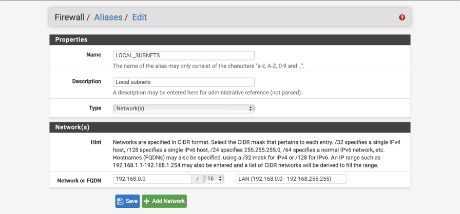
Define local subnets
We will create an alias to define the internal subnet we are using.
Navigate to Firewall > Aliases > IP
Click ‘+ Add’
- Name = LOCAL_SUBNETS
- Description = local subnets
- Type = Networks
- Network = 192.168.0.0
- CIDR = 16
- Comment = LAN (192.168.0.0 - 192.168.255.255)
Click Save
Define SELECTIVE_ROUTING addresses
I define a list of addresses to route out of the default WAN gateway to avoid unnecessary complications with banks and other services that object to traffic originating from known VPN end points. This alias creates an empty placeholder list for now. It is possible to use pfBlockerNG to enhance this functionality. (Edit: I recommend completing this guide, once everything is verified as working visit the pfBlockerNG guide).
Navigate to Firewall > Aliases > IP
- Click ‘+ Add’
- Name = SELECTIVE_ROUTING
- Description = IP address to exit VL20_VPN subnet via WAN gateway
- Type = Host(s)
Click Save
Define administration / anti-lockout ports
We will create a list to define which ports administration traffic flows on, we will allow these ports with a dedicated rule on key interfaces later to ensure we don’t lock ourselves out when configuring the firewall.
Navigate to Firewall > Aliases > Ports
- Click ‘+’
- Name = ADMIN_PORTS
- Description = Admin ports used for system administration
- Type = Ports
- 443 : pfSense web configurator
- 22 : pfsense SSH
Click Save
Define ports allowed to communicate between internal subnets
We will create a list of ports to define what traffic is permitted to traverse between local subnets. You will need to amend this alias as per your own networks requirements, but this should get you started. To better understand what needs you have, enable firewall logging and review the firewall logs which will illustrate which ports are being used or blocked.
Navigate to Firewall > Aliases > Ports
- Click ‘+’
- Name = Allowed_OUT_Ports_LAN
- Description = Ports permitted LAN egress
- Type = Ports
- Ports(s) =
- 53 : DNS
- 5353:5354 : MDNS
- 123 : NTP
- 21 : FTP
- 22 : SSH
- 161 : SNMP
- 80 : HTTP
- 443 : HTTPS
- 515 : LPD (Printer)
- 427 : SLP (Printer scanner)
- 631 : IPP (Printer)
- 8080:8081 : Unifi
- 8880 : Unifi redirect HTTP
- 8843 : Unifi redirect HTTPS
- 10001 : UBNT broadcast
- 5001 : iperf
- 5900 : IPMI
- 9000 : VNC
- 3389 : remote desktop
- 49152:65535 : Ephemeral ports
Click Save
Define ports allowed to access the internet
We will create a list of ports to define what is allowed to access the internet. You will need to amend this as per your own networks requirements. Again, if any programs or services you use stop working, check the firewall logs to see if there are any blocked ports being reported.
Navigate to Firewall > Aliases > Ports
- Click ‘+’
- Name = Allowed_OUT_Ports_WAN
- Description = Open WAN ports
- Type = Ports
- Ports(s) =
- 21 : FTP
- 22 : SSH
- 80 : HTTP
- 443 : HTTPS
- 587 : SMTPS
- 993 : IMAPS
- 5222 : XMPP
- 8080 : HTTP Alt
- 465 : SMTPS
- 119 : NNTP
- 143 : IMAP
- 6667 : IRC
- 6697 : IRCS
- 8443 : CalDAV
- 8843 : CardDAV
- 49152:65535 : ephemeral ports
Click Save
Setup Firewall Rules
Firewall are critical component of securing your network and its worth double checking you have this section set up correctly. Errors here could expose your network to unwanted intruders. I split my IPv4 and IPv6 default blocks out currently, but you could combine them into a single rule if you prefer. The order of the rules is important as they are processed from top to bottom. I’ve added images for each interface so you can verify your rules have been created and ordered correctly.
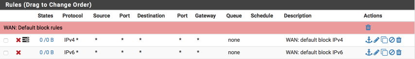
First, set up the WAN interface. With no rules, all inbound traffic is blocked by default but isn’t logged. Add a catch all rule that prevents and more importantly logs inbound traffic so we can be aware of who may be trying to gain access.
WAN rules
If there are two default rules already created on this page its likely you didn’t disable the autogeneration of rules options when you configured the WAN Interface. Click on the cog next to one of the two default rules and ensure the Block RFC1918 networks and Block BOGON network options are cleared. We will replace these with our specific rules to enable more fine-grained control.
Navigate to Firewall > Rules > WAN
- Click ‘↴+’
- Action = Block
- Disabled =
- Interface = WAN
- Address Family = IPv4
- Protocol = Any
- Source = Any
- Destination = Any
- Log =
- Description = WAN: default block IPv4
-
Click [Save]
- Click ‘↴+’
- Action = Block
- Disabled =
- Interface = WAN
- Address Family = IPv6
- Protocol = Any
- Source = Any
- Destination = Any
- Log =
- Description = WAN: default block IPv6
- Click [Save]
Your WAN interface should look this this when done. (I’ve added some separators to provide notes and aid readability, they aren’t a requirement though so feel free to omit if you prefer).
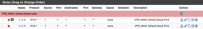
VPN_WAN rules
Now we will create similar block rules on the VPN_WAN interface to prevent and log any unwanted ingress. Rules on the OpenVPN tab will apply before the interface tabs and also to all OpenVPN interfaces. I recommend creating specific and targeted interface rules so leave the OpenVPN interface clear.
Navigate to Firewall > Rules > VPN_WAN and create the following rules:
A rule to block and log IPv4 traffic
- Click ‘↴+’
- Action: Block
- Disabled =
- Interface: VPN_WAN
- Address Family: IPv4
- Protocol: Any
- Source: Any
- Destination: Any
- Log:
- Description: VPN_WAN: default block IPv4
- Click [Save]
and a rule to block IPv6 traffic
- Click ‘↴+’
- Action: Block
- Disabled =
- Interface: VPN_WAN
- Address Family: IPv6
- Protocol: Any
- Source: Any
- Destination: Any
- Log:
- Description: VPN_WAN: default block IPv6
- Click [Save]
Your VPN_WAN interface should look this this when done.
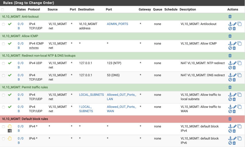
VL10_MGMT rules
My management interface requirements are:
- antilockout to ensure I can always gain access to pfSense.
- allow ICMP pings to facilitate debugging
- allow traffic to my local networks on approved ports
- allow internet traffic on approved ports
- redirect any non-local NTP time lookups back to our pfSense time server
- allow internal and external DNS resolution.
- reject any other traffic (note: we use reject rather than block on internal interfaces to provide a response to any programs trying to send traffic preventing delays associated with waiting for time outs to occur)
I’ve added some images in to help illustrate the correct way to complete the fields of the rule sheet.
Navigate to Firewall > Rules > VL10_MGMT and create the following rules:
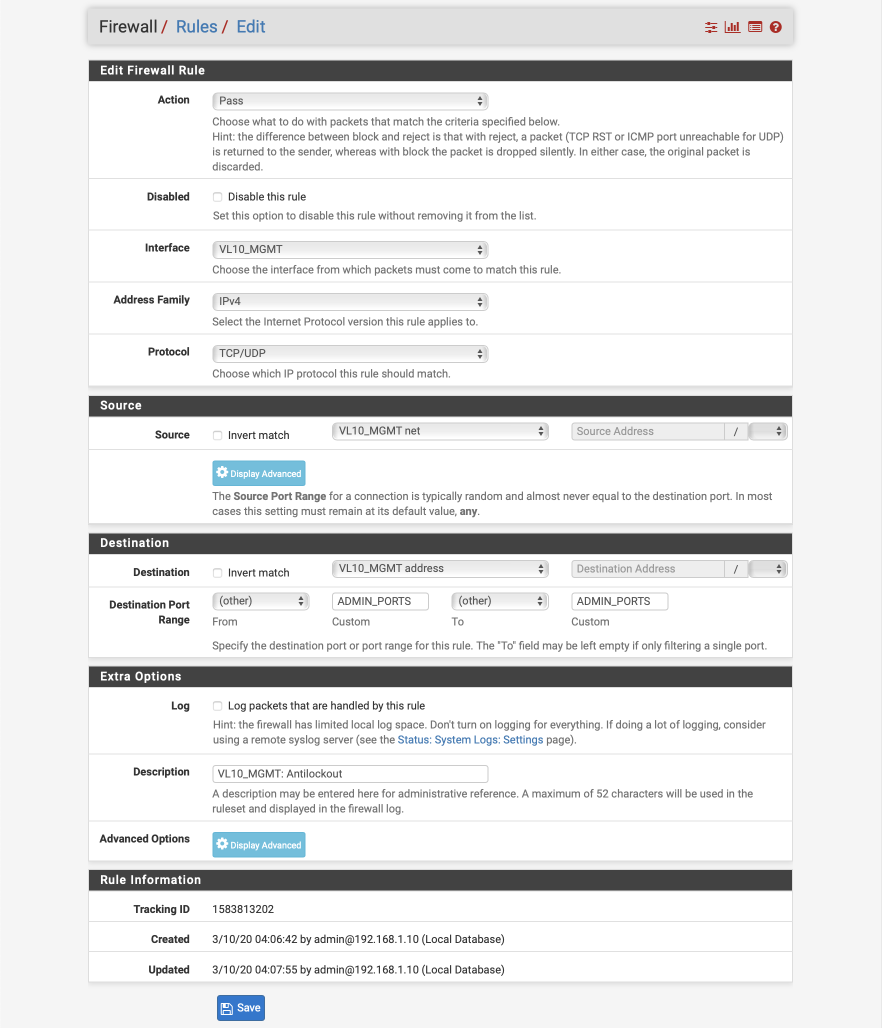
Create anti-lockout rule.
- Click ‘↴+’
- Action: Pass
- Disabled:
- Interface: VL10_MGMT
- Address Family: IPv4
- Protocol: TCP/UDP
- Source: VL10_MGMT net
- Destination: VL10_MGMT address
- Destination Port range:
- From: Other
- Custom: ADMIN_PORTS
- To: Other
- Custom: ADMIN_PORTS - Log:
- Description: VL10_MGMT: Antilockout
- Click [Save]
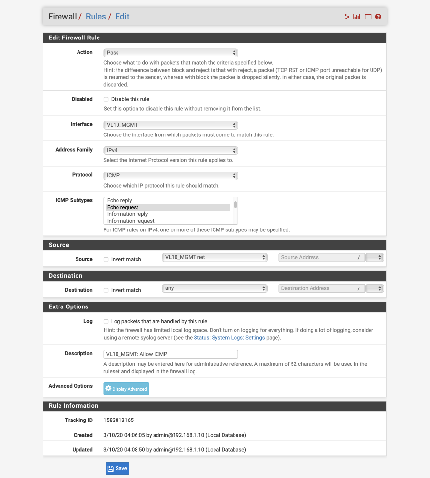
Create allow ICMP ‘ping’ debugging from management interface rule.
- Click ‘↴+’ icon
- Action: Pass
- Disabled:
- Interface: VL10_MGMT
- Address Family: IPv4
- Protocol: ICMP
- ICMP subtype: echo request
- Source: VL10_MGMT net
- Destination: Any
- Log:
- Description: VL10_MGMT: Allow ICMP
Create redirect for non-firewall NTP lookups
Navigate to Firewall > NAT and select Port Forward
Click Add
- Disabled:
- no RDR (NOT):
- Interface: VL10_MGMT
- Protocol: UDP
- Source: VL10_MGMT net
- Source port range:
- From: Any
- To: Any
- Destination:
- Invert Match:
- Source: VL10_MGMT address
- Destination target port range:
- From: NTP
- To: NTP
- Redirect target IP: 127.0.0.1
- Redirect target port: NTP
- Description: VL10_MGMT: NTP redirect
- No XMLRPC Sync:
- NAT reflection: Use system default
- Filter rule association: Add associated filter rule
Save & Apply
Create redirect for non-firewall DNS lookups
Click Add
- Disabled:
- no RDR (NOT):
- Interface: VL10_MGMT
- Protocol: TCP/UDP
- Source: VL10_MGMT net
- Source port range:
- From: Any
- To: Any
- Destination:
- Invert Match:
- Source: VL10_MGMT address
- Destination target port range:
- From: DNS
- To: DNS
- Redirect target IP: 127.0.0.1
- Redirect target port: DNS
- Description: VL10_MGMT: DNS redirect
- No XMLRPC Sync:
- NAT reflection: Use system default
- Filter rule association: Add associated filter rule
Save & Apply
Navigate back to Firewall > Rules and select VL10_MGMT.
You should see two rules created for the redirects for NTP and DNS at the bottom. Now lets create the remaining rules for this subnet.
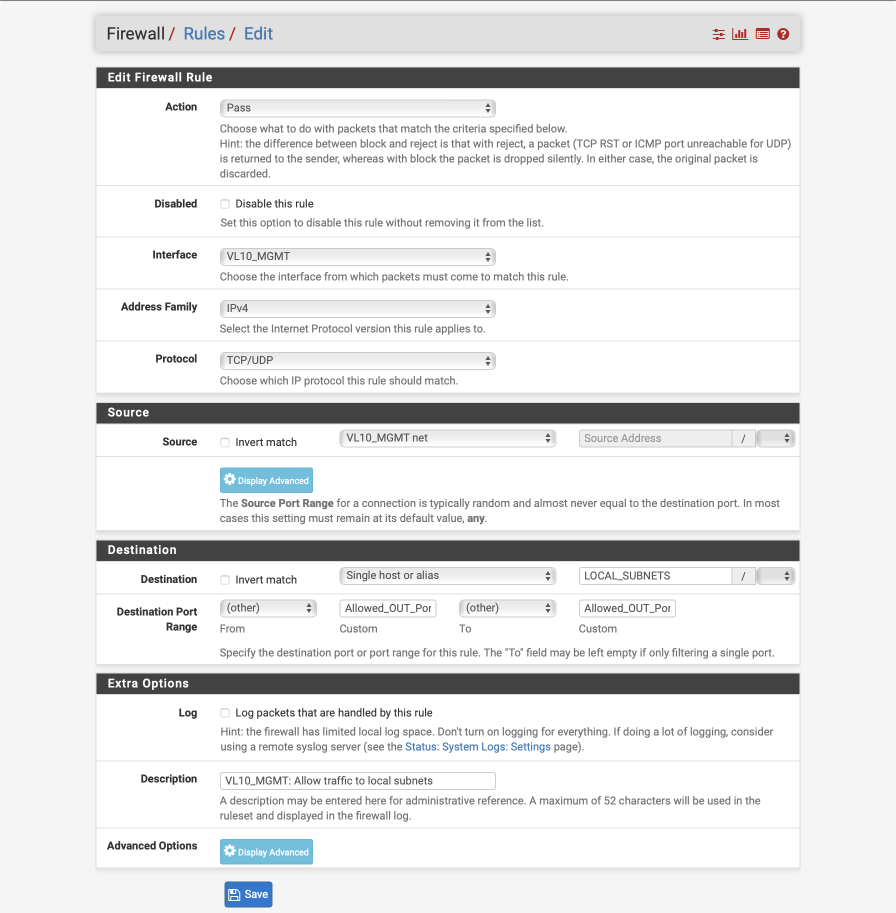
Create allow local traffic from management interface to all other subnets rule.
- Click ‘↴+’ icon
- Action: Pass
- Disabled:
- Interface: VL10_MGMT
- Address Family: IPv4
- Protocol: TCP/UDP
- Source: VL10_MGMT net
- Destination:
- Invert Match :
- Single Host or alias: LOCAL_SUBNETS - Destination Port Range:
- From: Other
- Custom: Allowed_OUT_Ports_LAN
- To: Other
- Custom: Allowed_OUT_Ports_LAN - Log:
- Description: VL10_MGMT: Allow traffic to local subnets
Create allow traffic from management interface to Internet rule
We identify traffic destined for the internet as to an interface which is NOT a LOCAL_SUBNETS.
- Click ‘↴+’ icon
- Action: Pass
- Disabled:
- Interface: VL10_MGMT
- Address Family: IPv4
- Protocol: TCP/UDP
- Source: VL10_MGMT net
- Destination:
- Invert Match :
- Single Host or alias: LOCAL_SUBNETS - Destination Port Range:
- From: Other
- Custom: Allowed_OUT_Ports_WAN
- To: Other
- Custom: Allowed_OUT_Ports_WAN - Log:
- Description: VL10_MGMT: Allow traffic to WAN

Create block unknown IPv4 rule
- Click ‘↴+’ icon
- Action: Reject
- Disabled:
- Interface: VL10_MGMT
- Address Family: IPv4
- Protocol: Any
- Source = Any
- Destination: Any
- Log =
- Description: VL10_MGMT: default block IPv4
- Click [Save]
Create block unknown IPv6 rule
- Click ‘↴+’ icon
- Action: Reject
- Disabled:
- Interface: VL10_MGMT
- Address Family: IPv6
- Protocol: Any
- Source: Any
- Destination: Any
- Log:
- Description: VL10_MGMT: default block IPv6
- Click [Save]
Your VL10_MGMT interface should look this this when done.
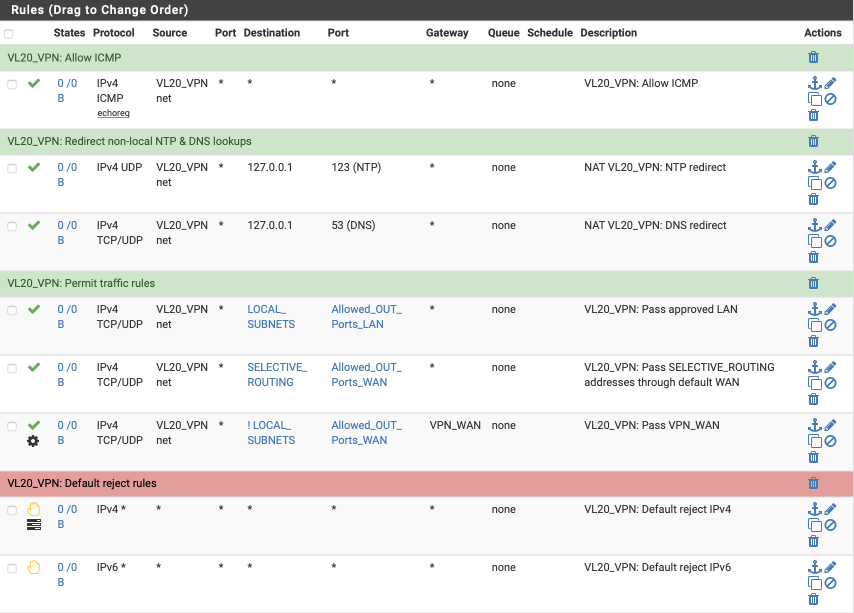
VL20_VPN rules
Now we will create the rules for our VPN and primary local interface, the requirements for this interface are:
- allow ICMP pings to facilitate debugging
- allow traffic to my local networks on approved ports
- allow select traffic egress via WAN gateway
- allow traffic egress via VPN gateway
- redirect any non-local NTP time lookups
- redirect any non-local DNS lookups
- reject any other traffic
Navigate to Firewall > Rules > VL20_VPN and create the following rules.
Create allow ICMP pings for network diagnostics rule
- Click ‘↴+’ icon
- Action: Pass
- Disabled =
- Interface: VL20_VPN
- Address Family: IPv4
- Protocol: ICMP
- ICMP subtype: echo request
- Source: VL20_VPN net
- Destination: Any
- Log:
- Description: VL20_VPN: Allow ICMP
Create redirect for non-firewall NTP lookups
Navigate to Firewall > NAT and select Port Forward
Click Add
- Disabled:
- no RDR (NOT):
- Interface: VL20_VPN
- Protocol: UDP
- Source: VL20_VPN net
- Source port range:
- From: Any
- To: Any
- Destination:
- Invert Match:
- Source: VL20_VPN address
- Destination target port range:
- From: NTP
- To: NTP
- Redirect target IP: 127.0.0.1
- Redirect target port: NTP
- Description: VL20_VPN: NTP redirect
- No XMLRPC Sync:
- NAT reflection: Use system default
- Filter rule association: Add associated filter rule
Save & Apply
Create redirect for non-firewall DNS lookups
Click Add
- Disabled:
- no RDR (NOT):
- Interface: VL20_VPN
- Protocol: TCP/UDP
- Source: VL20_VPN net
- Source port range:
- From: Any
- To: Any
- Destination:
- Invert Match:
- Source: VL20_VPN address
- Destination target port range:
- From: DNS
- To: DNS
- Redirect target IP: 127.0.0.1
- Redirect target port: DNS
- Description: VL20_VPN: DNS redirect
- No XMLRPC Sync:
- NAT reflection: Use system default
- Filter rule association: Add associated filter rule
Save & Apply
Navigate back to Firewall > Rules and select VL20_VPN.
You should see two rules created for the redirects for NTP and DNS at the bottom. Create the remaining rules for this subnet.
Create allow traffic to local subnets on permitted ports only rule.
We make use of the LOCAL_SUBNETS and Allowed_OUT_Ports_LAN aliases in this rule
- Click ‘↴+’
- Action: Pass
- Disabled =
- Interface: VL20_VPN
- Address Family: IPv4
- Protocol: TCP/UDP
- Source: VL20_VPN net
- Destination:
- invert match:
- Single host or alias:
- LOCAL_SUBNETS - Destination Port Range:
- From: Other
- Custom: Allowed_OUT_Ports_LAN
- To: Other
- Custom: Allowed_OUT_Ports_LAN - Log:
- Description: VL20_VPN: Pass approved LAN
- Click [Save]
Create selective routing rule for specified traffic to exit ISP WAN gateway.
Allow specified traffic to egress via the default unencrypted ISP gateway. This is useful for sites which block VPNs or require you to expose your true location, for example, banking sites.
- Click ‘↴+’
- Action: Pass
- Disabled =
- Interface: VL20_VPN
- Address Family: IPv4
- Protocol: TCP/UDP
- Source: VL20_VPN net
- Destination: Single Host or alias
- Address: SELECTIVE_ROUTING - Destination Port Range:
- From: Other
- Custom: Allowed_OUT_Ports_WAN
- To: Other
- Custom: Allowed_OUT_Ports_WAN - Log:
- Description: VL20_VPN: Pass SELECTIVE_ROUTING addresses through default WAN
- Click [Save]
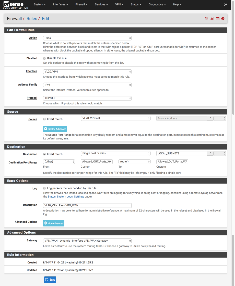
Create pass approved internet bound traffic out the VPN gateway
- Click ‘↴+’
- Action: Pass
- Disabled =
- Interface: VL20_VPN
- Address Family: IPv4
- Protocol: TCP/UDP
- Source: VL20_VPN net
- Destination:
- Invert Match:
- Single host or alias
- Address: LOCAL_SUBNETS - Destination Port Range:
- Invert match:
- From: Other
- Custom: Allowed_OUT_Ports_WAN
- To: Other
- Custom: Allowed_OUT_Ports_WAN - Log =
- Description: VL20_VPN: Pass VPN_WAN
- Click Advanced Options
- Gateway: VPN_WAN
- Click [Save]
Create default Block & log rules
- Click ‘↴+’
- Action: Reject
- Disabled =
- Interface: VL20_VPN
- Address Family: IPv4
- Protocol: Any
- Source: Any
- Destination: Any
- Log:
- Description: VL20_VPN: Default reject IPv4
- Click [Save]
Block default IPv6
- Click ‘↴+’
- Action: Reject
- Disabled =
- Interface: VL20_VPN
- Address Family: IPv6
- Protocol: Any
- Source: Any
- Destination: Any
- Log:
- Description: VL20_VPN: Default reject IPv6
- Click [Save]
VL20_VPN Summary
Your VL20_VPN interface should look this this when done.
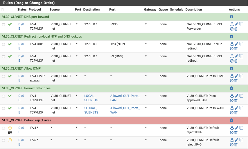
VL30_CLRNET rules
Now we will create the rules for our unencrypted ‘clearnet’ local interface, the requirements for this interface are:
- allow ICMP pings to facilitate debugging
- allow traffic to local networks on approved ports
- allow internet traffic on approved ports via default gateway
- redirect any non-local NTP time lookups
- redirect any non-local DNS lookups
- reject any other traffic
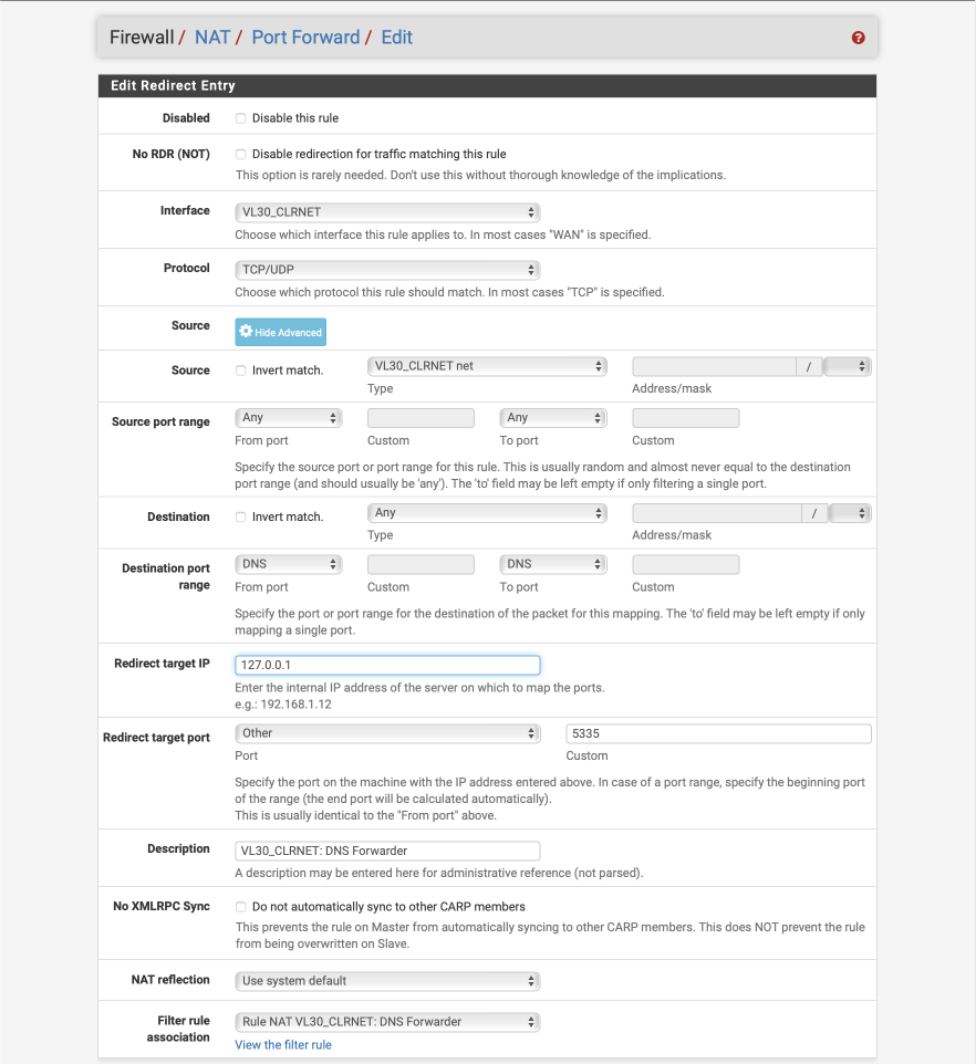
DNS Forwarder redirect
As clients perform DNS lookups on port 53 by default, we will create a port forward to forward traffic on VL30_CLRNET from port 53 to the Forwarder listening on localhost on port 5335.
Navigate to Firewall > NAT and select Port Forward
Click Add
- Disabled =
- No RDR (NOT) =
- Interface = VL30_CLRNET
- Protocol = TCP/UDP
- Source = VL30_CLRNET
- Source port range:
- From: Any
- To: Any
- Destination = Any
- Source port range:
- From: DNS
- To: DNS
- Redirect target IP = 127.0.0.1
- Redirect target port
- Port = Other
- Custom = 5335
- Description = VL30_CLRNET: DNS Forwarder
- No XMLRPC Sync =
- NAT reflection = Use system default
- Filter rule association = Add associated filter rule
Click Save & Apply changes
The redirect entry should look like this
Create redirect for non-firewall NTP lookups
Click Add
- Disabled:
- no RDR (NOT):
- Interface: VL30_CLRNET
- Protocol: UDP
- Source: VL30_CLRNET net
- Source port range:
- From: Any
- To: Any
- Destination:
- Invert Match:
- Source: VL30_CLRNET address
- Destination target port range:
- From: NTP
- To: NTP
- Redirect target IP: 127.0.0.1
- Redirect target port: NTP
- Description: VL30_CLRNET: NTP redirect
- No XMLRPC Sync:
- NAT reflection: Use system default
- Filter rule association: Add associated filter rule
Save & Apply
Create redirect for non-firewall DNS lookups
Click Add
- Disabled:
- no RDR (NOT):
- Interface: VL30_CLRNET
- Protocol: TCP/UDP
- Source: VL30_CLRNET net
- Source port range:
- From: Any
- To: Any
- Destination:
- Invert Match:
- Source: VL30_CLRNET address
- Destination target port range:
- From: DNS
- To: DNS
- Redirect target IP: 127.0.0.1
- Redirect target port: DNS
- Description: VL30_CLRNET: DNS redirect
- No XMLRPC Sync:
- NAT reflection: Use system default
- Filter rule association: Add associated filter rule
Save & Apply
Navigate back to Firewall > Rules and select VL30_CLRNET.
You should see three rules created for the redirects for NTP and DNS. Now let’s create the remaining rules for this subnet.
Create allow Pings for network diagnostics rule
- Click ‘↴+’
- Action: Pass
- Disabled =
- Interface: VL30_CLRNET
- Address Family: IPv4
- Protocol: ICMP
- ICMP subtype: echo request
- Source: VL30_CLRNET net
- Destination: Any
- Log:
- Description: VL30_CLRNET: Pass ICMP
- Click [Save]
Create allow traffic to local subnets on permitted ports only rule.
We make use of the Allowed_OUT_Ports_LAN & LOCAL_SUBNETS aliases here again.
- Click ‘↴+’
- Action: Pass
- Disabled =
- Interface: VL30_CLRNET
- Address Family: IPv4
- Protocol: TCP/UDP
- Source: VL30_CLRNET net
- Destination:
- invert match:
- Single host or alias
- LOCAL_SUBNETS - Destination Port Range:
- From: Other
- Custom: Allowed_OUT_Ports_LAN
- To: Other
- Custom: Allowed_OUT_Ports_LAN - Log:
- Description: VL30_CLRNET: Pass approved LAN
- Click [Save]
Create pass approved internet bound traffic out the default system gateway, i.e not the VPN connection rule
- Click ‘↴+’
- Action: Pass
- Disabled =
- Interface: VL30_CLRNET
- Address Family: IPv4
- Protocol: TCP/UDP
- Source: VL30_CLRNET net
- Destination:
- Invert Match:
- Single host or alias
- LOCAL_SUBNETS - Destination Port Range:
- From: Other
- Custom: Allowed_OUT_Ports_WAN
- To: Other
- Custom: Allowed_OUT_Ports_WAN - Log:
- Description:VL30_CLRNET: Pass WAN
- Click [Save]
Create default block & log rules
- Click ‘↴+’
- Action: Reject
- Disabled =
- Interface: VL30_CLRNET
- Address Family: IPv4
- Protocol: Any
- Source: Any
- Destination:Any
- Log:
- Description: VL30_CLRNET: Default reject IPv4
- Click [Save]
Default block IPv6
- Click ‘↴+’
- Action: Reject
- Disabled =
- Interface: VL30_CLRNET
- Address Family: IPv6
- Protocol: Any
- Source: Any
- Destination Any
- Log:
- Description: VL30_CLRNET: Default reject IPv6
- Click [Save]
VL30_CLRNET Summary
Your VL30_CLRNET interface should look this this when done.
VL40_GUEST
Our GUEST network is a special case. Critically, we do not allow guests access to access any internal devices or subnets. The requirements for the guest interface are:
- allow ICMP pings to facilitate debugging
- deny traffic to pfSense WAN, VPN or other interfaces
- deny traffic to any local networks
- allow internet traffic via default gateway
- allow non-local NTP time lookups
- allow guest > guest network traffic
- allow non-local DNS lookups (DHCP allocates public DNS Servers)
- reject any other traffic
Navigate to Firewall > Rules > VL40_GUEST and create the following rules:-
Create deny traffic to pfsense WAN, VPN or other interfaces
This_Firewall is an alias that represents all the interfaces on your pfSense box including VPNs, WANS etc.
- Click ‘↴+’
- Action = Reject
- Disabled =
- Interface = VL40_GUEST
- Address Family = IPv4
- Protocol = TCP/UDP
- Source = VL40_GUEST net
- Destination = This Firewall
- Destination port range: ADMIN_PORTS
- Log =
- Description = VL40_GUEST: Reject pfsense admin interfaces
- Click [Save]
Create allow Pings for network diagnostics.
- Click ‘↴+’
- Action = Pass
- Disabled =
- Interface = VL40_GUEST
- Address Family = IPv4
- Protocol = ICMP
- ICMP subtype = echo request
- Source = VL40_GUEST net
- Destination = Any
- Log =
- Description = VL40_GUEST: Pass ICMP
- Click [Save]
Create allow guest access the internet uncensored rule
This permits the external access including DNS/port 53 and NTP/port 123 traffic.
- Click ‘↴+’
- Action = Pass
- Disabled =
- Interface = VL40_GUEST
- Address Family = IPv4
- Protocol = TCP/UDP
- Source = VL40_GUEST net
- Destination
- invert match:
- Single host or alias
- Address: LOCAL_SUBNETS - Destination Port Range:
- From: Any
- To: Any - Log =
- Description = VL40_GUEST: Pass WAN
- Click [Save]
Create block rule to any local networks.
I also log any matches of this rule so I can see if any of my guests are attempting to access my local networks.
- Click ‘↴+’
- Action = Reject
- Disabled =
- Interface = VL40_GUEST
- Address Family = IPv4
- Protocol = TCP/UDP
- Source = VL40_GUEST net
- Destination
- invert match:
- Single host or alias
- Address: LOCAL_SUBNETS - Destination Port Range:
- From: Any
- To: Any - Log =
- Description = VL40_GUEST: Reject any local traffic
- Click [Save]
Create default block & log rules
- Click ‘↴+’
- Action = Reject
- Disabled =
- Interface = VL40_GUEST
- Address Family = IPv4
- Protocol = Any
- Source = Any
- Destination:Any
- Log =
- Description = VL40_GUEST: Default reject IPv4
- Click [Save]
Default block IPv6
- Click ‘↴+’
- Action = Reject
- Disabled =
- Interface = VL40_GUEST
- Address Family = IPv6
- Protocol = any
- Source = Any
- Destination: Any
- Log =
- Description = VL40_GUEST: Default reject IPv6
- Click [Save]
VL40_GUEST Summary
Your VL40_GUEST interface should look this this when done.
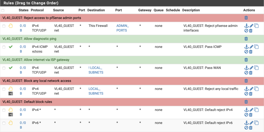
LAN
My LAN interface is treated rather differently. It’s mainly used for debugging and as such it can be reconfigured from time to time. As an initial setup I usually configure it with the following requirements in mind.
- provide anti-lockout via admin ports
- allow ICMP pings to facilitate debugging
- allow any traffic to local subnets
- allow any traffic to internet via default gateway, not VPN
- reject any other traffic
Navigate to Firewall > Rules > LAN and create the following rules:-
Create anti-lockout rule
Create the anti-lockout rule ensuring we can always gain access to the GUI and the shell.
- Click ‘↴+’
- Action: Pass
- Disabled =
- Interface: LAN
- Address Family: IPv4
- Protocol: TCP/UDP
- Source: LAN net
- Destination: LAN address
- Destination Port range:
- From: Other
- Custom: ADMIN_PORTS
- To: Other
- Custom: ADMIN_PORTS - Log:
- Description: LAN: Antilockout
- Click [Save]
Create the rule to allow ICMP pings
- Click ‘↴+’
- Action: Pass
- Disabled =
- Interface: LAN
- Address Family: IPv4
- Protocol: ICMP
- ICMP subtype: echo request
- Source: LAN net
- Destination: Any
- Log:
- Description: LAN: Pass ICMP
- Click [Save]
Create pass all traffic, local or internet bound
- Click ‘↴+’
- Action: Pass
- Disabled =
- Interface: LAN
- Address Family: IPv4
- Protocol: TCP/UDP
- Source: LAN net
- Destination: Any
- Destination Port range:
- From: Any
- To: Any - Log:
- Description: LAN: Pass All
- Click [Save]
Create default block & log rules
- Click ‘↴+’
- Action: Reject
- Disabled =
- Interface: LAN
- Address Family: IPv4
- Protocol: Any
- Source: Any
- Destination: Any
- Log:
- Description: LAN: Default reject IPv4
- Click [Save]
Default block IPv6
- Click ‘↴+’
- Action: Reject
- Disabled =
- Interface: LAN
- Address Family: IPv6
- Protocol: Any
- Source: Any
- Destination: Any
- Log:
- Description: LAN: Default reject IPv6
- Click [Save]
LAN Summary
Your LAN interface should look this this when done.
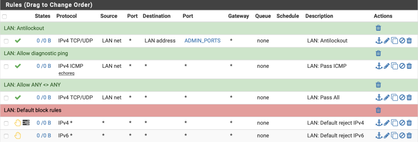
Reboot
This would be a good time to restart your firewall box and connect your modem to your WAN port if you haven’t already. The system should boot and allow you to log back into the dashboard where if everything is correct, the WAN and VPN_WAN interfaces will have IP addresses allocated to them.
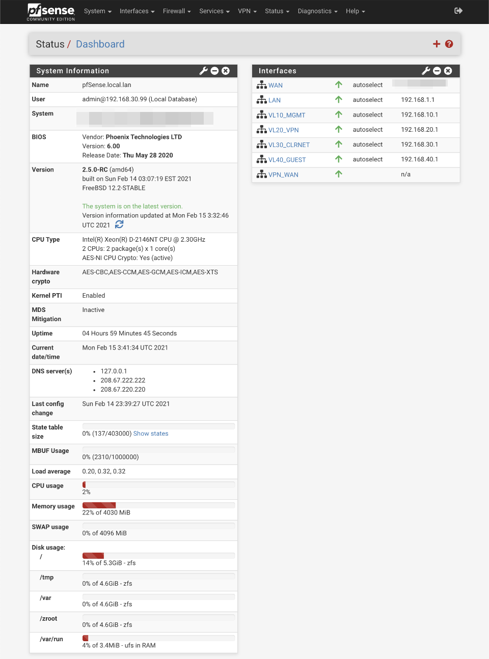
If things don’t work as expected, make use of the system logs by navigating to Status > System Logs. The various tabs there will allow you to investigate all areas of the firewall and help you track down any issues.
Verification of functionality and performance
Connect up your managed switch and assuming you have correctly configured the trunk port and tagged LAN ports you should be able to go ahead and test the various subnets work correctly. There are some switch configuration guides for popular and cheap models available from the index page.
Verify DHCP
Connect to each subnet in turn and verify a client receives an appropriate address from the associated DHCP pool. Heres the connection when connected to the VL20_VPN network where a 192.168.20.100 address has been awarded.
$ ifconfig en0
en0: flags=8963<UP,BROADCAST,SMART,RUNNING,PROMISC,SIMPLEX,MULTICAST> mtu 1500
    ether xx:xx:xx:xx:xx:xx
    inet6 fe80::bae8:56ff:fe30:905e%en0 prefixlen 64 scopeid 0x4
    inet 192.168.20.100 netmask 0xffffff00 broadcast 192.168.20.255
    nd6 options=1<PERFORMNUD>
    media: autoselect
    status: active
Verify DNS.
We have three methods of DNS resolution to verify:
- VL20_VPN: uses Resolver for local and non-local lookups. External DNS servers’ requests are redirected back to pfSense.
- VL30_CLRNET: uses Forwarder for non-local and DNS Resolver for local. External DNS servers’ requests are redirected back to pfSense.
- VL40_GUEST: uses public DNS resolvers. No local lookups should be possible.
VL20_VPN
Verify DNS Resolver resolution
In these examples I’ll use ‘dig’ (domain information groper) command to resolve IP address.
$ dig pfsense.org

; <<>> DiG 9.10.6 <<>> pfsense.org
;; global options: +cmd
;; Got answer:
;; ->>HEADER<<- opcode: QUERY, status: NOERROR, id: 20952
;; flags: qr rd ra; QUERY: 1, ANSWER: 1, AUTHORITY: 0, ADDITIONAL: 1

;; OPT PSEUDOSECTION:
; EDNS: version: 0, flags:; udp: 4096
;; QUESTION SECTION:
;pfsense.org.			IN	A

;; ANSWER SECTION:
pfsense.org.		261	IN	A	208.123.73.69

;; Query time: 2 msec
;; SERVER: 192.168.20.1#53(192.168.20.1)
;; WHEN: Fri Mar 27 14:26:22 PDT 2020
;; MSG SIZE  rcvd: 56
Verify non-local DNS Resolver resolution.
Use the dig command and force the DNS query to use Googles DNS server (8.8.8.8). This should be redirected back to the pfSense DNS resolver for lookup.
$ dig @8.8.8.8 pfsense.org

; <<>> DiG 9.10.6 <<>> @8.8.8.8 pfsense.org
; (1 server found)
;; global options: +cmd
;; Got answer:
;; ->>HEADER<<- opcode: QUERY, status: NOERROR, id: 4847
;; flags: qr rd ra; QUERY: 1, ANSWER: 1, AUTHORITY: 0, ADDITIONAL: 1

;; OPT PSEUDOSECTION:
; EDNS: version: 0, flags:; udp: 4096
;; QUESTION SECTION:
;pfsense.org.			IN	A

;; ANSWER SECTION:
pfsense.org.		232	IN	A	208.123.73.69

;; Query time: 2 msec
;; SERVER: 8.8.8.8#53(8.8.8.8)
;; WHEN: Fri Mar 27 14:26:51 PDT 2020
;; MSG SIZE  rcvd: 56
Verify DNS Resolver’s local name resolution.
I use nslookup to lookup my pfSense gateway by its hostname and verify the address is returned correctly.
$ dig pfsense.local.lan

; <<>> DiG 9.10.6 <<>> pfsense.local.lan
;; global options: +cmd
;; Got answer:
;; ->>HEADER<<- opcode: QUERY, status: NOERROR, id: 44388
;; flags: qr aa rd ra; QUERY: 1, ANSWER: 1, AUTHORITY: 0, ADDITIONAL: 1

;; OPT PSEUDOSECTION:
; EDNS: version: 0, flags:; udp: 4096
;; QUESTION SECTION:
;pfsense.local.lan.		IN	A

;; ANSWER SECTION:
pfsense.local.lan.	3600	IN	A	192.168.1.1

;; Query time: 2 msec
;; SERVER: 192.168.20.1#53(192.168.20.1)
;; WHEN: Fri Mar 27 14:35:35 PDT 2020
;; MSG SIZE  rcvd: 62
Verify DNS Resolver reverse resolution.
Verify you can resolve a hostname from an IP address
$ dig +noall +answer -x 192.168.1.1
1.1.168.192.in-addr.arpa. 3600	IN	PTR	pfSense.local.lan.
Verify DNS Resolver ‘.local.lan’ domain resolution.
My DNS Resolver is defined as authoritative for my local.lan domain. If I try and lookup an address which is not part of my network, it will return status: NXDOMAIN rather than forward the lookup to external DNS resolvers.
$ dig nothere.local.lan

; <<>> DiG 9.8.3-P1 <<>> nothere.local.lan
;; global options: +cmd
;; Got answer:
;; ->>HEADER<<- opcode: QUERY, status: NXDOMAIN, id: 18955
;; flags: qr aa rd ra; QUERY: 1, ANSWER: 0, AUTHORITY: 1, ADDITIONAL: 0

;; QUESTION SECTION:
;nothere.local.lan.     IN  A

;; AUTHORITY SECTION:
local.lan.      10800   IN  SOA pfsense.local.lan. root.local.lan. 1 3600 1200 604800 10800

;; Query time: 4 msec
;; SERVER: 192.168.20.1#53(192.168.20.1)
;; WHEN: Sun Aug 27 10:22:30 2017
;; MSG SIZE  rcvd: 84
VL30_CLRNET
Verify DNS Forwarder resolution.
The server response is correctly displayed as 192.168.30.1
$ dig pfsense.org

; <<>> DiG 9.10.6 <<>> pfsense.org
;; global options: +cmd
;; Got answer:
;; ->>HEADER<<- opcode: QUERY, status: NOERROR, id: 1174
;; flags: qr rd ra; QUERY: 1, ANSWER: 1, AUTHORITY: 0, ADDITIONAL: 1

;; OPT PSEUDOSECTION:
; EDNS: version: 0, flags:; udp: 4096
;; QUESTION SECTION:
;pfsense.org.			IN	A

;; ANSWER SECTION:
pfsense.org.		300	IN	A	208.123.73.69

;; Query time: 230 msec
;; SERVER: 192.168.30.1#53(192.168.30.1)
;; WHEN: Fri Mar 27 14:58:08 PDT 2020
;; MSG SIZE  rcvd: 56
Verify non local DNS Forwarder lookups
Use the dig command and force the DNS query to use Googles DNS server (8.8.8.8). This should be redirected back to the pfSense DNS resolver for resolution. Dig is unable to correctly identify the true source of the name resolution and assumes it was a response from the target servers, in this example 8.8.8.8. The low query response time of 2 msec suggests that this wasn’t actually the case. More through testing is possible using a packet sniffer but this is beyond the scope opt this guide.
$ dig @8.8.8.8 pfsense.org

; <<>> DiG 9.10.6 <<>> @8.8.8.8 pfsense.org
; (1 server found)
;; global options: +cmd
;; Got answer:
;; ->>HEADER<<- opcode: QUERY, status: NOERROR, id: 43195
;; flags: qr rd ra; QUERY: 1, ANSWER: 1, AUTHORITY: 0, ADDITIONAL: 1

;; OPT PSEUDOSECTION:
; EDNS: version: 0, flags:; udp: 4096
;; QUESTION SECTION:
;pfsense.org.			IN	A

;; ANSWER SECTION:
pfsense.org.		235	IN	A	208.123.73.69

;; Query time: 2 msec
;; SERVER: 8.8.8.8#53(8.8.8.8)
;; WHEN: Fri Mar 27 14:59:12 PDT 2020
;; MSG SIZE  rcvd: 56
Verify DNS Resolver’s local name resolution.
This is handled by the forwarding rule to the DNS Resolver.
$ dig pfsense.local.lan

; <<>> DiG 9.10.6 <<>> pfsense.local.lan
;; global options: +cmd
;; Got answer:
;; ->>HEADER<<- opcode: QUERY, status: NOERROR, id: 39629
;; flags: qr aa rd ra; QUERY: 1, ANSWER: 1, AUTHORITY: 0, ADDITIONAL: 1

;; OPT PSEUDOSECTION:
; EDNS: version: 0, flags:; udp: 4096
;; QUESTION SECTION:
;pfsense.local.lan.		IN	A

;; ANSWER SECTION:
pfsense.local.lan.	1	IN	A	192.168.1.1

;; Query time: 2 msec
;; SERVER: 192.168.30.1#53(192.168.30.1)
;; WHEN: Fri Mar 27 15:00:22 PDT 2020
;; MSG SIZE  rcvd: 62
VL40_GUEST
Verify DNS Resolver resolution
Note the server resolving should be the DNS servers we configured in the General tab, in this example, 208.67.222.222 and not pfSense itself.
$ dig pfsense.org

; <<>> DiG 9.10.6 <<>> pfsense.org
;; global options: +cmd
;; Got answer:
;; ->>HEADER<<- opcode: QUERY, status: NOERROR, id: 5451
;; flags: qr rd ra; QUERY: 1, ANSWER: 1, AUTHORITY: 0, ADDITIONAL: 1

;; OPT PSEUDOSECTION:
; EDNS: version: 0, flags:; udp: 4096
;; QUESTION SECTION:
;pfsense.org.			IN	A

;; ANSWER SECTION:
pfsense.org.		87	IN	A	208.123.73.69

;; Query time: 17 msec
;; SERVER: 208.67.222.222#53(208.67.222.222)
;; WHEN: Fri Mar 27 15:01:40 PDT 2020
;; MSG SIZE  rcvd: 56
VL40_GUEST isolation.
Connect to the VL40_GUEST network and verify you can’t access the pfSense web configurator. Also verify you can’t access other systems and local devices you have connected to other subnets.
Verify VPN connection
Open a browser and head over to AirVPN.org.
For the GUEST and CLRNET subnets you should observe your own IP address instead.

For the VPN subnet you should see a valid connection to a AirVPN server in the header bar.

It’s worth checking the crpyt selected as part of the connection process. Navigate to Status > System Logs and Select OpenVPN. Here’s a section from a successful connection with our intended data channel AES-256-GCM cipher.
OpenVPN 2.5.0 amd64-portbld-freebsd12.2 [SSL (OpenSSL)] [LZO] [LZ4] [MH/RECVDA] [AEAD] built on Feb  5 2021
library versions: OpenSSL 1.1.1i-freebsd  8 Dec 2020, LZO 2.10
MANAGEMENT: unix domain socket listening on /var/etc/openvpn/client1/sock
mlockall call succeeded
NOTE: the current --script-security setting may allow this configuration to call user-defined scripts
Initializing OpenSSL support for engine 'rdrand'
WARNING: experimental option --capath /var/etc/openvpn/client1/ca
Outgoing Control Channel Encryption: Cipher 'AES-256-CTR' initialized with 256 bit key
Outgoing Control Channel Encryption: Using 256 bit message hash 'SHA256' for HMAC authentication
Incoming Control Channel Encryption: Cipher 'AES-256-CTR' initialized with 256 bit key
Incoming Control Channel Encryption: Using 256 bit message hash 'SHA256' for HMAC authentication
Control Channel MTU parms [ L:1621 D:1156 EF:94 EB:0 ET:0 EL:3 ]
Data Channel MTU parms [ L:1621 D:1450 EF:121 EB:406 ET:0 EL:3 ]
Local Options String (VER=V4): 'V4,dev-type tun,link-mtu 1601,tun-mtu 1500,proto UDPv4,cipher AES-256-CBC,auth SHA512,keysize 256,key-method 2,tls-client'
Expected Remote Options String (VER=V4): 'V4,dev-type tun,link-mtu 1601,tun-mtu 1500,proto UDPv4,cipher AES-256-CBC,auth SHA512,keysize 256,key-method 2,tls-server'
TCP/UDP: Preserving recently used remote address: [AF_INET]199.249.223.132:443
Socket Buffers: R=[42080->524288] S=[57344->524288]
UDPv4 link local (bound): [AF_INET]xxx.xxx.xxx.xxx:0
UDPv4 link remote: [AF_INET]199.249.223.132:443
TLS: Initial packet from [AF_INET]199.249.223.132:443, sid=2bdb5ead 8890b169
VERIFY WARNING: depth=0, unable to get certificate CRL: C=IT, ST=IT, L=Perugia, O=airvpn.org, CN=Aquila, emailAddress=info@airvpn.org
VERIFY WARNING: depth=1, unable to get certificate CRL: C=IT, ST=IT, L=Perugia, O=airvpn.org, CN=airvpn.org CA, emailAddress=info@airvpn.org
VERIFY OK: depth=1, C=IT, ST=IT, L=Perugia, O=airvpn.org, CN=airvpn.org CA, emailAddress=info@airvpn.org
VERIFY KU OK
Validating certificate extended key usage
++ Certificate has EKU (str) TLS Web Server Authentication, expects TLS Web Server Authentication
VERIFY EKU OK
VERIFY OK: depth=0, C=IT, ST=IT, L=Perugia, O=airvpn.org, CN=Aquila, emailAddress=info@airvpn.org
WARNING: 'link-mtu' is used inconsistently, local='link-mtu 1601', remote='link-mtu 1602'
WARNING: 'comp-lzo' is present in remote config but missing in local config, remote='comp-lzo'
Control Channel: TLSv1.3, cipher TLSv1.3 TLS_CHACHA20_POLY1305_SHA256, 4096 bit RSA
[Aquila] Peer Connection Initiated with [AF_INET]199.249.223.132:443
PUSH: Received control message: 'PUSH_REPLY,comp-lzo no,redirect-gateway  def1 bypass-dhcp,dhcp-option DNS 10.9.190.1,route-gateway 10.9.190.1,topology subnet,ping 10,ping-restart 60,ifconfig 10.9.190.15 255.255.255.0,peer-id 2,cipher AES-256-GCM'
OPTIONS IMPORT: timers and/or timeouts modified
OPTIONS IMPORT: compression parms modified
OPTIONS IMPORT: --ifconfig/up options modified
OPTIONS IMPORT: route options modified
OPTIONS IMPORT: route-related options modified
OPTIONS IMPORT: --ip-win32 and/or --dhcp-option options modified
OPTIONS IMPORT: peer-id set
OPTIONS IMPORT: adjusting link_mtu to 1624
OPTIONS IMPORT: data channel crypto options modified
Data Channel: using negotiated cipher 'AES-256-GCM'
Data Channel MTU parms [ L:1552 D:1450 EF:52 EB:406 ET:0 EL:3 ]
Outgoing Data Channel: Cipher 'AES-256-GCM' initialized with 256 bit key
Incoming Data Channel: Cipher 'AES-256-GCM' initialized with 256 bit key
ROUTE_GATEWAY xxx.xxx.xxx.xxx/255.255.248.0 IFACE=ixl1 HWADDR=xx:xx:xx:df:09:ed
TUN/TAP device ovpnc1 exists previously, keep at program end
TUN/TAP device /dev/tun1 opened
do_ifconfig, ipv4=1, ipv6=0
/sbin/ifconfig ovpnc1 10.9.190.15 10.9.190.1 mtu 1500 netmask 255.255.255.0 up
/sbin/route add -net 10.9.190.0 10.9.190.1 255.255.255.0
/usr/local/sbin/ovpn-linkup ovpnc1 1500 1552 10.9.190.15 255.255.255.0 init
Initialization Sequence Completed
Verify no DNS leaks
Open a browser and head over to DNSLeaktest.com.
To validate functionality run an extended leak test on each subnet. If you find the test doesn’t start correctly, disable ‘Experimental Bit 0x20 Support’ under the DNS Resolver’s advanced settings and try again.
It’s important to verify that the VL20_VPN subnet isn’t leaking and only identifies a single DNS server resolved via an AirVPN end point.
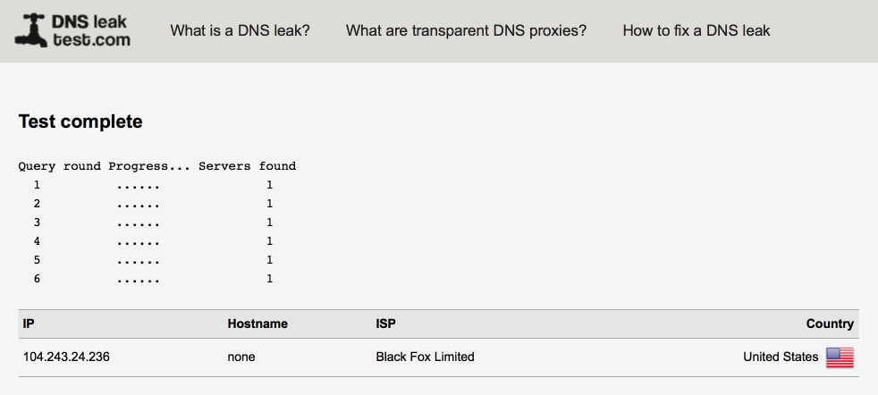
My VL30_CLRNET subnet shows several OpenDNS servers as configured under the general configuration tab. As the DNS Resolver is enabled as a DNS server for the firewall, 127.0.0.1 will be added to the list of servers queried and this is why you will notice a lookup served via the VPN tunnel also.
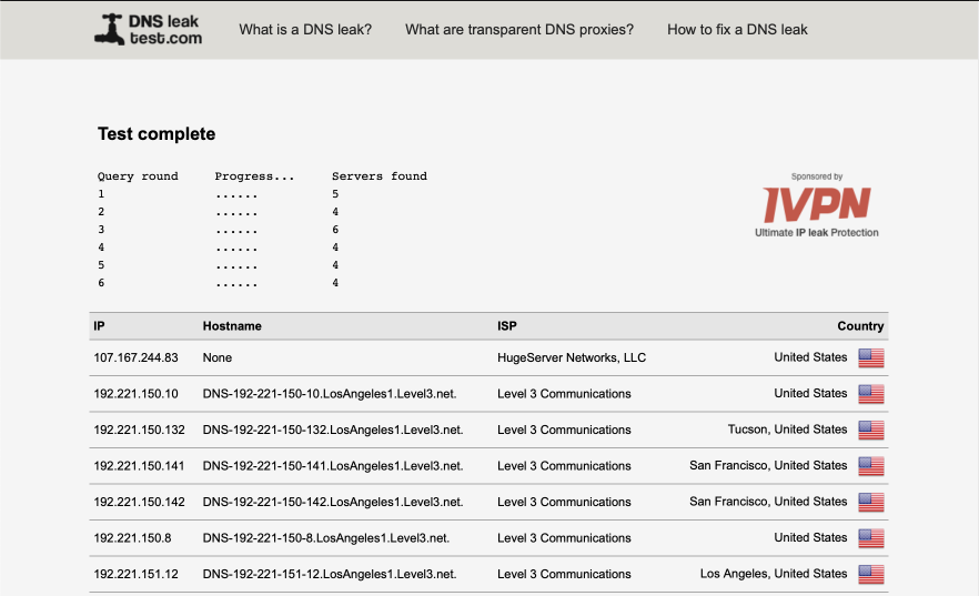
My VL40_GUEST network as expected shows up multiple ISP servers.
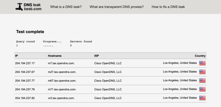
VPN Performance
VPN performance will depend on your hardware and also fluctuate depending on server load especially during peak times. With a nearby server I would look for a 15ms increase in ping times and a reduction in throughput of around 10% of the hardware capabilities.
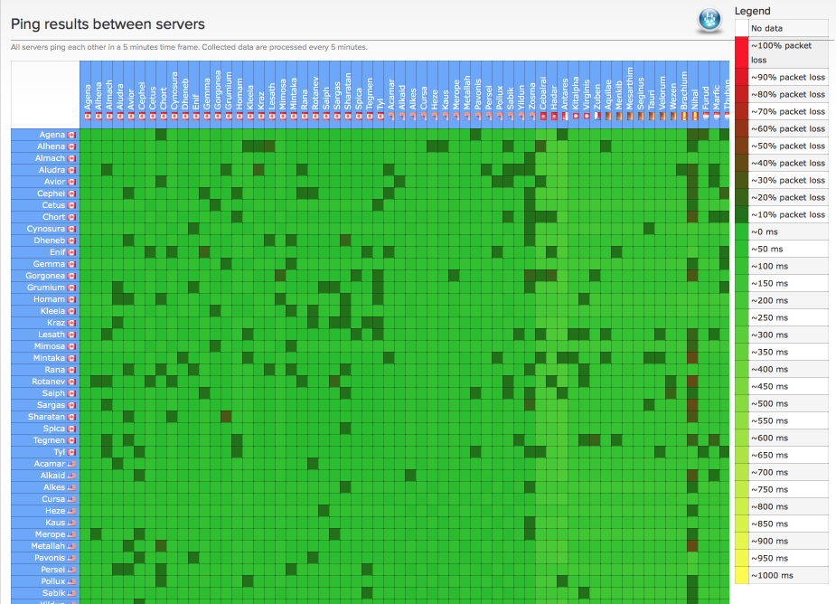
I validated performance with speedtest.net.
Here’s my LAN performance illustrating Verizon’s FIOS 150/150 service performance.
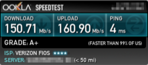
and here’s my VL20_VPN performance
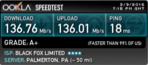
References
pfSense documentation
pfSense book
CIDR notation
RFC1918
Changelog
27 February 2021
Minor additions for clarity
20 February 2021
Revised for pfSense v2.5.0
25 June 2020
Additional network interface configuration details added
20 April 2020
Added reference link to pfBlockerNG guide
13 April 2020
Added further DNS Resolver details
Updated DNS leak test results
1 April 2020
Corrected typos, added some additional details.
28 March 2020
Corrected typos
27 March 2020
Major Revision for pfSense v2.4.5
28 January 2018
Added link to SG300 switch guide
11 December 2017
Fixed typos & inconsistencies in images
25 November 2017
Misc typo’s fixed
2 November 2017
Added Unifi guide link
Correct error in VL10_MGMT interface image
Fixed DNS leak test link
29 August 2017
Updated destination field in DNS port forward
Updated strict interface binding setting in DNS Forwarder