In part 1 we left off with a video showing some semi-stable flight
However, as my mother would say, it doesn’t look stable at all. It just drifts around and crashes. And as much as she doesn’t appreciate how hard PID controllers are, she has a point. So the next step would be to figure out how to get a more stable and controlled flight. Eventually I was able to get to a flight that looked like this:
It’s much more stable and controllable (and yes my apartment is a lot cleaner 😅). There’s still some wobbliness and I’m not truly happy with how it responds to my control inputs, so there will be a part 3 where I dial those things in. For now though, I’d like to talk about how I improved the capabilities of the drone from that first version.
There’s three things that jump out as unstable about that first video, the altitude, the xy velocity (i.e. drifting left/right and forward/back), and the heading (notice how it lazily spins as it takes off).
Tracking altitude turns out to be fairly simple. Hobby level barometers are sensitive to pressure changes of as little as +/-0.5 Pa, which translates to about +/-5cm of altitude. It might even be possible to combine accelerometer measurements through a Kalman filter to get even more accuracy. Time of Flight (ToF) sensors can also provide altitude, but since they’re reflecting off the ground, flying over a cluttered area can cause bad readings if you don’t have the appropriate logic to detect jumps, and so it seemed like a barometer would be an easier, more robust solution.
X and Y velocity can be handled in one of two ways. Firstly I can simply connect some sort of controller, i.e. an xbox controller, and control the X and Y velocity manually. This is something I would want to do anyway in order to have some control over the drone. Secondly I could use an optical flow sensor to automatically control the X/Y velocity. These are not mutually exclusive, of course, but I decided that in the spirit of making small improvements I would start out with the controller and I would design my PCB to be extensible to allow for adding an optical flow sensor later on.
However it would be difficult to use a controller given the spinning behavior you see in the first video. Either the drone’s heading needed to be stabilized, or the controller’s commands needed to be converted into the drone coordinate frame. In either case the solution is to use a magnetometer.
In the following sections I expand on how I dealt with all three of these topics, including challenges that I faced along the way.
While the datasheet for my pressure sensor of choice, the BMP581, claims a relative pressure accuracy of +/- 0.4 Pa, and probably delivers it when the pressure is actually constant, the data it delivers when sitting on my desk paints a different picture.
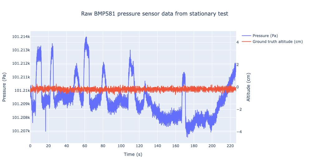
The sensor is sitting on my desk in my apartment. My door is closed, my window is closed, and my AC is off. And yet we see three rather concerning behaviors. The first is the spikes around 10s, 22s, 60s, and others. The second is the slow drift which is most noticeable in the last 20-30 seconds of the graph. And the third is that when sitting still the readings range over +/-3.5 Pa, which translates to +/-35cm of altitude.
I decided to see if I could improve this by combining the accelerometer data. I built a little test platform that included the pressure sensor, the accelerometer, as well as a Time of Flight (ToF) sensor to measure distance to the ground to act as a ground truth for whatever method I chose to use to combine the two sensors. Ultimately I was able to develop and tune a Kalman filter to provide a passable looking estimate of the vertical velocity.
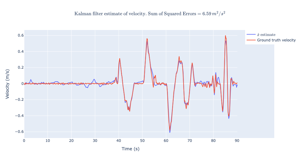
To get the estimate this good I had to modify the process noise and sensor noise matrices (Q and R) of the Kalman filter dynamically. When acceleration was low I would increase Q relative to R, i.e. increase my trust in the accelerometer measurements, otherwise I would increase R relative to Q and trust the barometer more. This worked reasonably well for estimating vertical velocity, but it was not very good for estimating altitude.
At the end of the day, in the interest of making progress, I decided to use the altitude as reported by the barometer with a low pass filter applied to take out some of the noise, and accept the consequences. Ultimately it worked fairly well and made flying the drone a lot easier by not having to think about the altitude too much, but this is something I’d like to revisit in version 3 to see if I can do better.
As part of trying to “track” xy velocity I set about trying to trim the drone. Essentially I would hang the drone by a string in its flight configuration (with battery attached and connected) and wait for it to settle. From there I could read the readings of pitch and roll and add weight in the right spots (with extra nuts/washers) to get the readings to be 0 and 0.
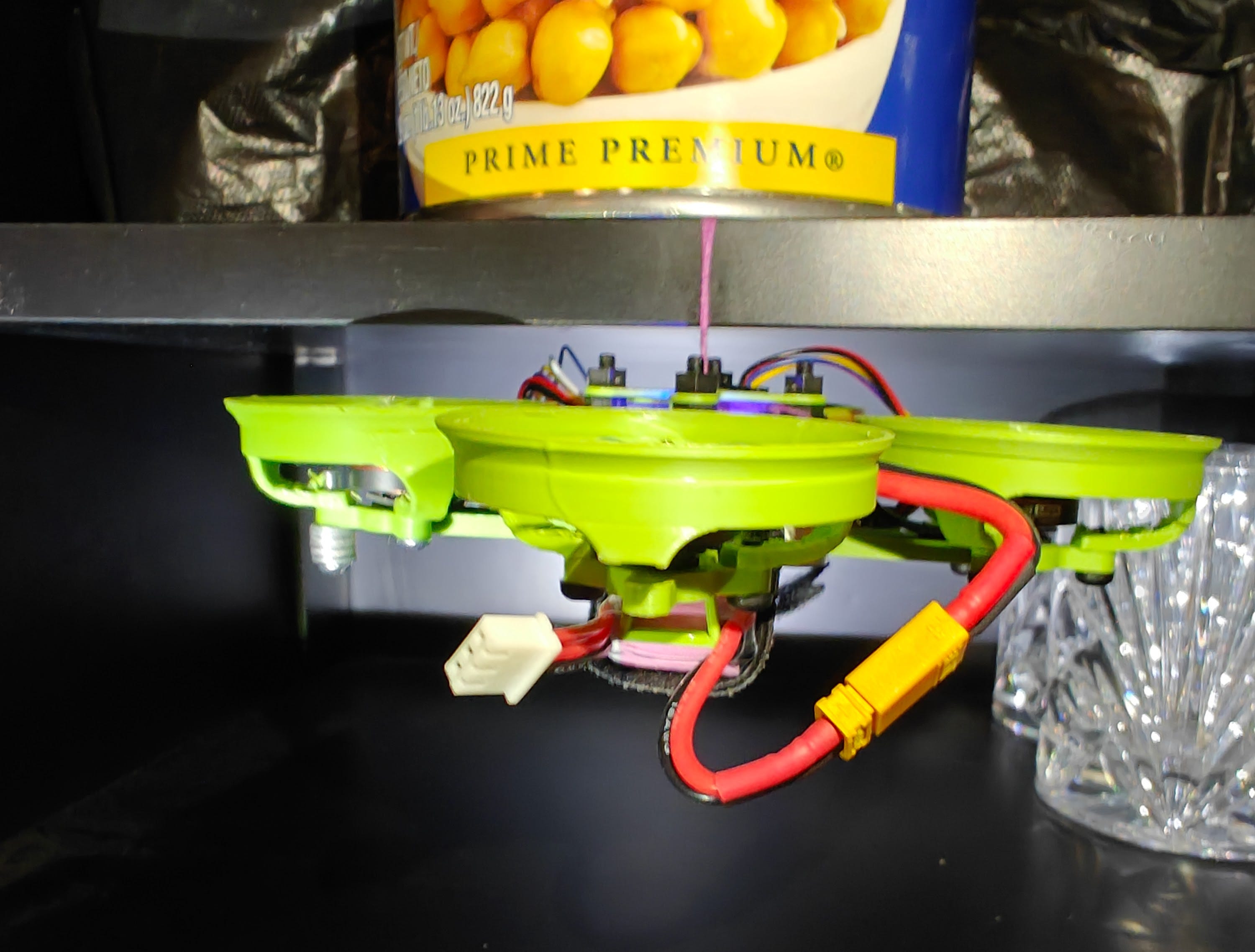
With this setup it was difficult to get better than 0.5 degrees of error, since there’s some static friction in the string/drone interface that’s hard to get rid of, but surely 0.5 degrees is enough?
Surprisingly no. Despite trimming the drone, it still exhibited significant drift in both pitch and roll during test flights. Ultimately I added an in-flight configurable trim, which I would adjust with the controller’s Dpad, and this got us to relatively stable flight.
I can’t explain why it needs so much trim in flight. Presumably there are differences in the motors, and one potential avenue of investigation it to see if my ESC supports reverse DShot for telemetry to see what RPMs the motors are actually running at vs what is commanded. It’s also possible that due to oddities in my frame (i.e. the way the battery is mounted and connected) there are differences in airflow and therefore lift from the different motors, but visual inspection doesn’t reveal anything that looks like a smoking gun.
The magnetometer had some interesting challenges. First of all, due to issues with my power circuitry, the magnetometer that I had built into the PCB only worked when the board was powered off of 5V USB, and completely ceased to operate when power came from the 8V battery. I wrote about this issue separately. There was no solution to this specific issue, but fortunately I had added a Qwiic connector to the board just in case I needed to add sensors, and this allowed me to add an offboard magnetometer.
The magnetometer needed some calibration. When moving it though a variety of different orientations the various axes did not produce symmetric readings, and so I would average out the max and min readings and subtract this from the nominal readings going forward. I’m told this is due to “hard iron” offsets, i.e. distortions in the magnetic field from nearby components that produce magnetic fields (i.e. the magnets in the motors, for example). There are also soft iron offsets, which distort the magnetic field as opposed to offsetting it. I took a brief look at soft iron offsets in my setup, but they seemed to be minimal so I did not pursue the matter much further. Vectornav has an excellent writeup about these distortions and how to deal with them.
Separately from the 3 points mentioned above, my drone was very noisy and had a very short flight time. I was using 0702 motors (07 is the radius, 02 is the height, both in mm) with 31mm diameter propellers, because I was initially aiming for a 4V system for my drone, but was forced to switch to 8V due to the fact that I couldn’t find any 4V all-in-one ESCs (at least, no standalone ones that didn’t come with a flight computer, which was important to me since I’m the one building the flight computer), and the 0702 motors were the only 8V ones I had lying around.
They required about 70-75% throttle just to stay in the air and had a flight time of only ~45 seconds at best. This made working with the drone rather difficult as I frequently had to swap out batteries. Actually, one of the improvements I’d made to v2 was to route the battery voltage to one of the analog pins on the ESP32 so that I could read voltage and know how much battery I had left! This was a major quality of life improvement. There were many times previously where I had found myself investigating potential control system issues only to swap batteries and see that everything was fine.
After I got things flying stably I switch to 1102 motors with 41mm propellers. In the picture below you can see 1 of the new motors/propellers alongside the old ones
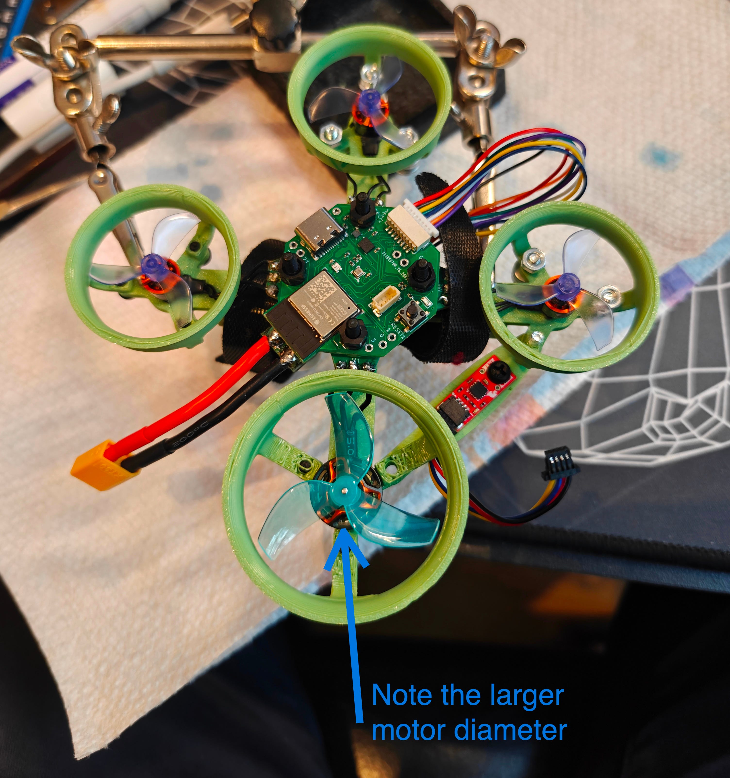
The new motors were a significant improvement. The throttle required to stay in the air was now only 40%, almost half of what it was before, despite the weight going up by about 12%. Flight times correspondingly nearly doubled, making it much easier to work with the drone.
In short, the following improvements were made to the drone for version 2:
A barometer was added to track altitude, which resulted in significant improvements in subjective controllability and performance.
A magnetometer was added to track heading, which stabilized the spin rates and allowed for adding a controller.
Support for a controller was added which allowed for much longer flight times
Bigger, more efficient motors and propellers were added to further increase flight times
Typical flight time was increased from 3-5s to 90s
There were a number of smaller improvements as well, including a programmable LED to help identify when initialization completed, as well as the aforementioned voltage reading to help identify battery level.
The drone still exhibits some wobbliness when flying, and it doesn’t respond as accurately to my control inputs as I’d like. If I command +17 degrees pitch, it will only get up to +9 degrees. Modifying the controller gains has helped to close that gap, but doesn’t close it completely and in some cases starts to introduce stability problems. Until now I’ve just been modifying PID gains ad-hoc and I’d like to try to approach the problem more rigorously. I hear Bode plots can help with stability and performance analysis of control systems, so I’d like to try creating one of those. There are other topics in control systems that I can learn about. But overall the next step here is:
Improve the control system to respond more quickly and accurately to control inputs while maintaining stability in level flight.
Additionally, having automatic control of X and Y velocity would be nice, so I’d like to experiment with adding an optical flow sensor.
Add an optical flow sensor to automatically control X and Y velocity.
Thanks for reading, I hope you got something useful out of this, and stay tuned for part 3!