For a long time I’ve wanted to play around with various concepts in controls engineering. I’ve studied concepts like quaternions, kinematics, Kalman filters, etc., but I feel like you never really learn and internalize these sorts of concepts until you actually build something with them, so in the fall of 2025 I decided to build my own drone “from scratch” in order to get a chance to implement these things first hand.
As the late Carl Sagan so eloquently put it “to make an apple pie from scratch, you must first invent the universe.”
In this case I decided to purchase motors, propellers, and the Electronic Speed Controller (ESC), and I would build the flight computer and frame on my own. Building the flight computer was a logical step because in dealing with kinematics and Kalman filters and things of this nature, the choice of sensor is crucial and something I felt I needed experience with, even if it meant making mistakes. Choosing my own sensors naturally means that I need to design my own electronics to support and integrate those sensors, but I decided to draw the line at the ESC as far as the electronics went. ESCs are available for purchase, and while I think I’d learn a lot from making my own ESC, that’s an entire project in and of itself, so it made sense to limit the scope to the flight computer.
The frame is something I expected to be relatively straightforward to make on a 3D printer.
My very first question was what sort of IMU do I pick? I hear the consumer grade ones are noisy, but how bad are they?
I started out by buying the cheapest sensor I could on Sparkfun: the BMI270 from Bosch.
I broke out my textbook from CU Boulder’s ASEN 5010: Spacecraft Attitude Dynamics and Control and started to implement the kinematic differential equations.
However, I got a lot of garbage. It would initially track orientation sort of ok, but very quickly it would turn to garbage. I scoured my code for some bug, and tested various pieces of it, but I still got garbage. I implemented a simple 2D orientation tracker and rotated the IMU about 1 axis only, and this seemed to give somewhat reasonable data, but the 3D orientation tracking wasn’t working. I started to conclude that maybe it was too noisy, and that it was meant more for detecting large motions like flipping your wrist than more fine grained attitude control.
And then I saw that I was multiplying by milliseconds where I should have been multiplying by seconds.
And suddenly it worked -
Later research showed me that I could use a Madgwick filter to combine the accelerometer and gyroscope measurements to keep the orientation right side up even when it drifts. Since I didn’t have a magnetometer the heading would have to be left to drift but I figured a slow drift is probably fine.
I know how to solder. I mean, I know the basics! But I don’t have much practice. On the left was my first attempt to solder my motor wires to the ESC, and on the right is a second attempt after getting some advice from /r/soldering. They were quite brutal, but ultimately helpful.


But soldering was the easy part, because despite claiming that it supported PWM, the ESC would not respond to any of the signals coming from my development board. I tried all sorts of PWM widths and settings. I tried moving from 0 throttle to 100 to see if I could get it calibrated, but nothing.
Long story short, the ESC wasn’t running the firmware it claimed to be running, and the firmware that was actually on it had deprecated PWM in favor of a new digital protocol for drones known as DShot. Very fortunately for me, the ESP32C3 has a peripheral called RMT (from ReMoTe) which was initially meant for working with remote controls, but can be programmed to send arbitrary digital signals, and even more fortunately their example program showed how to use it to implement DShot, yay!
Probably should’ve secured the motor, but it was just a test
This was the point when things really started to crystallize. I was able to detect and track orientation, I was able to spin a motor, now I could start putting things together.
With the electronics effectively tested I could now make a PCB to integrate all of these things instead of the breadboard setup you see in the video above. PCBs seem daunting at first. There are all these little components on them, all these capacitors and resistors and how are you supposed to figure out the values you need for them?
Well, it turns out the datasheets for the components you choose usually tell you what resistor/capacitor/etc. values to use, and it’s even easier when you can copy Sparkfun’s schematics (thanks for open sourcing your schematics SF!).
KiCAD is relatively straightforward, and within a week I had my PCB design.


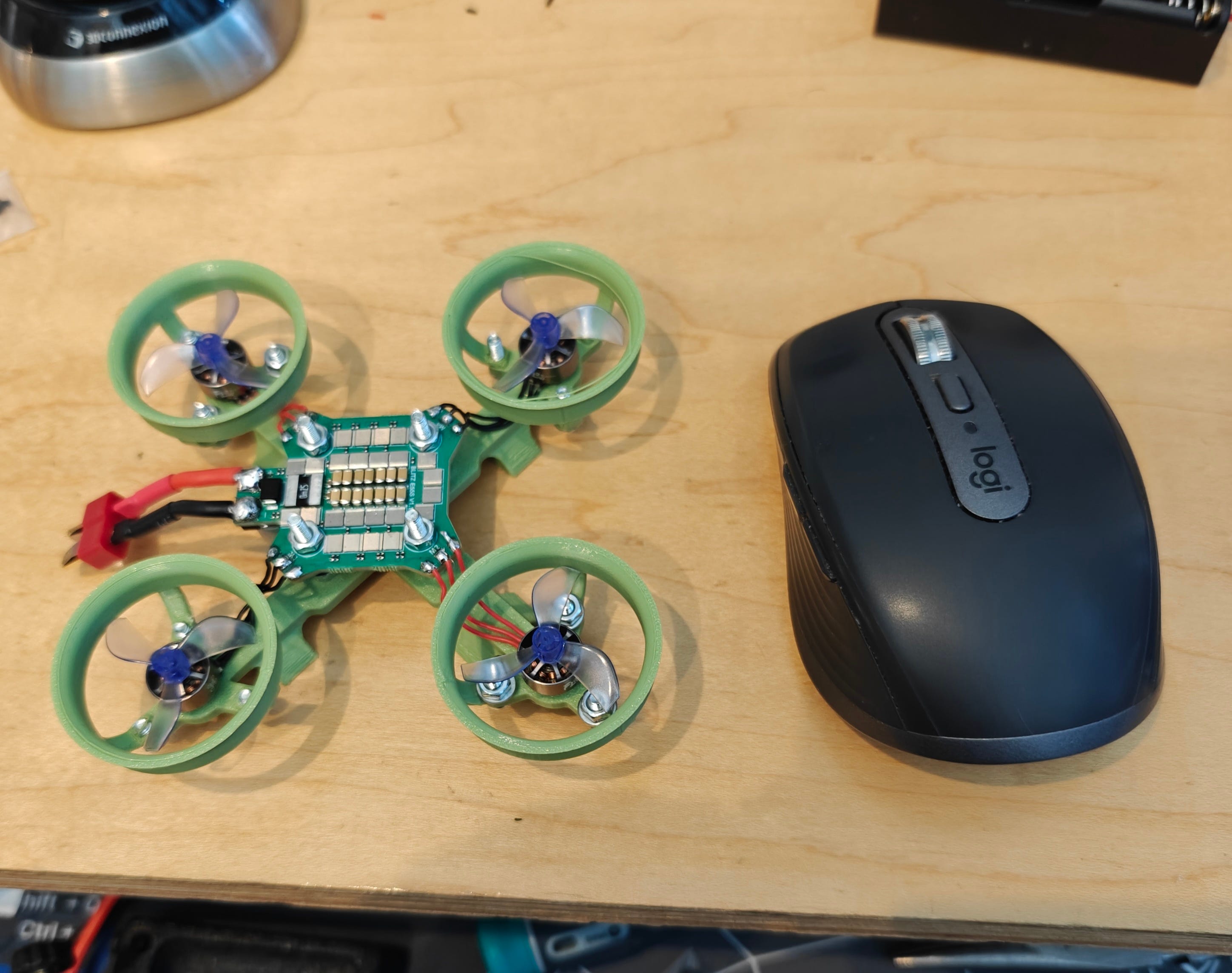
Making the frame took about a day of iterating with my 3D printer. It’s undoubtedly too heavy and too reliant on heavy nuts and bolts to keep things together, but after putting it on a scale and calculating the thrust of the motors I anticipated that it would still be able to fly.
After only 10 days I received the PCB from the manufacturer


I just want to stop for a second and point out how amazing all of this is. As a solo hobbyist I can make PCBs, I can 3D print frames, program microcontrollers. It’s an amazing world we live in.
I was happy to see that my PCB worked and accepted code as soon as I plugged it in, but I quickly realized there was a problem as I started replicating the code I wrote for the RMT (the code that spun the propeller in the above video) for four motors. The RMT only has 2 channels. I need to independently control 4 motors (if the drone has tilted each motor will need to apply a slightly different amount of thrust to get it back to stable). I briefly considered if I could do something like rapidly switch which two motors the RMT was controlling, but discarded that idea. In a best case I would have a working setup that was very janky, and in a worst case scenario I wouldn’t be able to switch fast enough to send the control signals in a timely manner.
I had two choices: switch to a microcontroller which has enough RMTs, which would mean redesigning the board and redoing manufacturing, which would take 2 weeks, or try to implement this DShot protocol on my own in software. I chose the latter approach, as I didn’t want to be down for two weeks, although I couldn’t be sure that I could do this in software. I didn’t know how sensitive this protocol is to timing, and if it required continuous sending I would be hosed because I can’t spend 100% of my CPU cycles on sending this protocol, I need some cycles to track the orientation and run the control loops. But manually screwing around with GPIO has served me well in my career so I decided to give it a go.
Fortunately I had access to an oscilloscope so I was able to check my timings
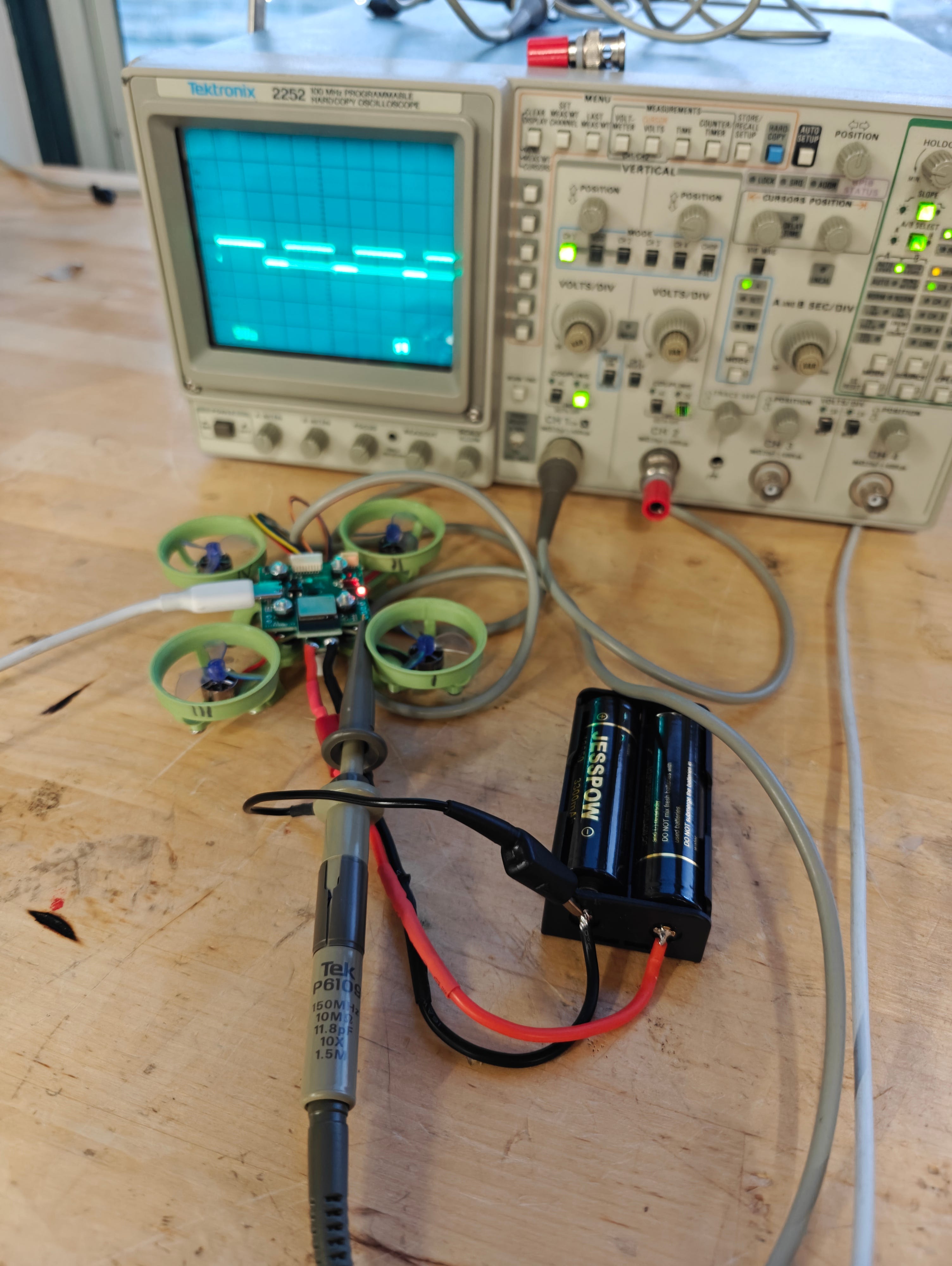
Although in actuality I didn’t get access to that oscilloscope until later, and at first I had to do this sort of blind, but eventually the bit-banging approach worked and all 4 motors were spinning!
All of the pieces were now in place, the Madgwick filter, the DShot protocol, the frame, the motors, the soldering, all that was left was to actually get it to fly, which was not easy.
There are effectively 3 PID loops that need to be tuned simultaneously. One for roll and pitch (technically this is two but since the drone is symmetrical we can use the same values for both), one for altitude, and one for yaw rate. Initially I thought maybe I could just focus on the first two, but the drone starts spinning very quickly if you allow the yaw rate to float, and then it becomes difficult to analyze what’s going on with roll and pitch, so controlling yaw rate is necessary.
While there are methods to characterize a system and determine PID values from that characterization, the drone needed to be flying for those characterizations to be possible. Otherwise the forces acting on the system (i.e. normal force from sitting on a table) are not representative of the forces which are acting on the system in flight. So the only real option was to just pick some values, see what happens, and try to iterate.
It started slowly
You gotta start somewhere…
The journey of 1000 miles begins with the first step, and the second step is usually pretty similar to the first.
It actually lifted off a little that time!
After finding a pretty serious typo in my code where I used the P gain twice instead of P and D gains, I actually started to get some stable flight.
The battery attachment uses velcro zip ties which kept sticking to the carpet
Getting to the point of stable flight required a ton of work, learning a couple new skills, and dealing with some challenges along the way, but boy did I learn a lot. And yet a drone which just flies up and wanders off until it crashes is not very interesting, so part II will cover adding control to the drone, which will cover both manual input as well as adding more sensors to automate certain aspects of the control.
UPDATE: Part II is now up