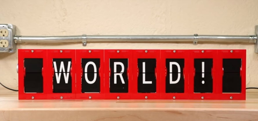
Split-flap displays are electromechanical display devices, which were common in airports or railway stations a few years ago.Unfortunately, most of them are gone and replaced by LED displays. Why not create a DIY version of it?

As mechanical devices they are rather complex and subject of mechanical wear-out. But Split-Flap displays have many advantages over their LED counterparts: no power required if the display is static, good visibility and contrast, and the flapping sound draws attention if information changes.
Luckily, there is an open source project by Scott Bezek which helps you building your own DIY Split-Flap display. :-).
Starting Point
The project started with a link a good friend forwarded to me (thanks again, James!), pointing to blog article by Dave Madison which shows how he has built a split-flap display: https://www.partsnotincluded.com/building-diy-split-flap-displays/
This amazing project is based on the outstanding work of Scott Bezek: https://scottbez1.github.io/splitflap/
If you need to know how such a display works:
I really like his mechanical design, and with the needed equipment available (laser-cutter, desktop CNC, PnP, …) this project was in reach for me :-).
The original project uses Arduino plus dedicated controller board. For many reasons I did not want to use Arduino. Instead, I wanted to build a system which can be used in the lab for my ‘Advanced Distributed Systems’ course, and this means using non-hobby software and development tools. Scott’s original design can drive up to 12 units, but I needed to have something which can be interconnected and distributed: giving each student one or more split-flap and have them connected and working with the units of other students. With this, I created a new driver/controller hardware and software.
If you want to build your own: start with Scott’s excellent documentation. What I describe here is how I created my version, so you can decide and pick what you want to use for your own build. Ideally you are able to assemble electronics, have access to a laser cutter and/or CNC. If you don’t want to build everything yourself: Scott is selling components from his Etsy store too.
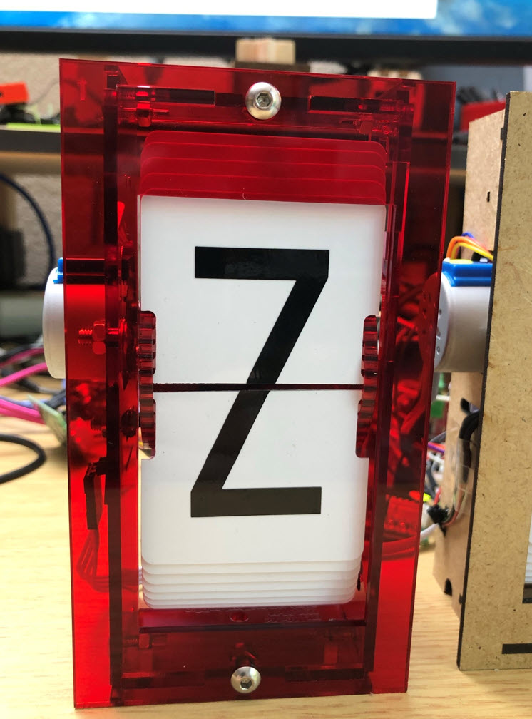
Enclosure
I re-used the original design from Scott with minor modifications, and created both 3 mm MDF and acrylic versions of it.
For the MDF I used 60×60 cm sheets which get cut into pieces by the CNC:
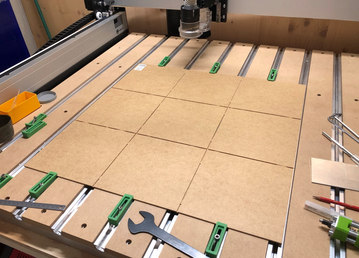
A laser cutter then cuts the parts out of each piece:

Similar for the PMMA/Acrylic version:

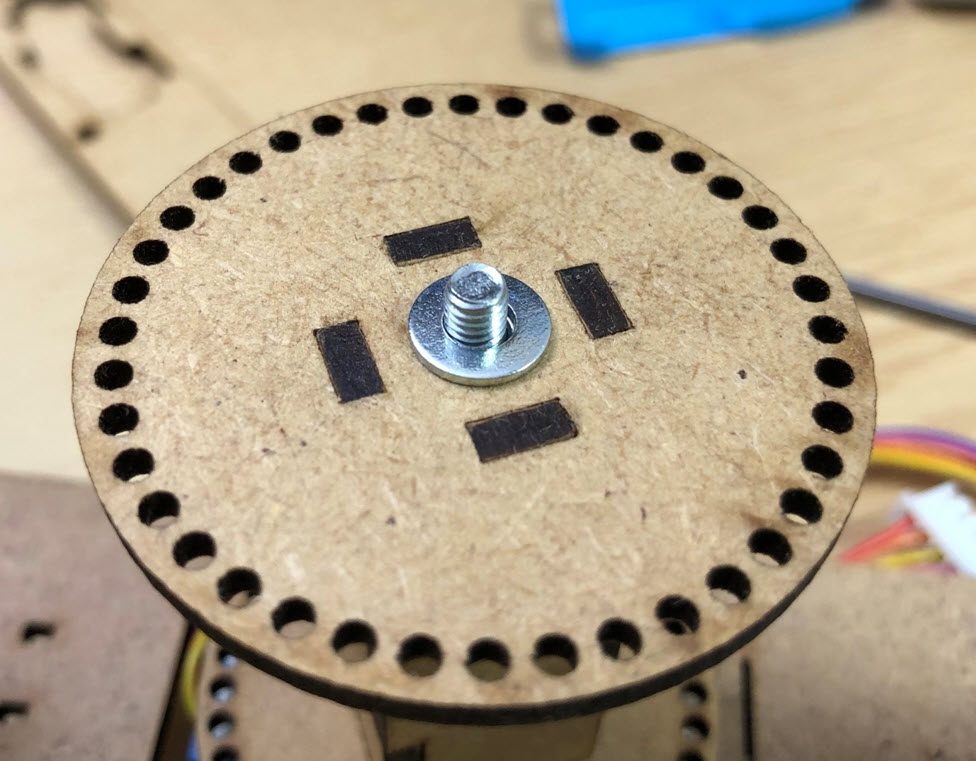
One modification was to add a washer to every spool:
I wanted to have a way to stack units:
A 3D printed connectors keeps them on top of each other:
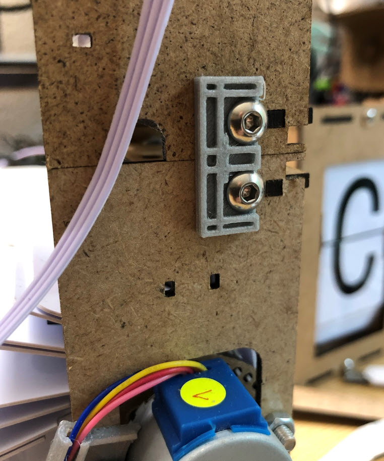
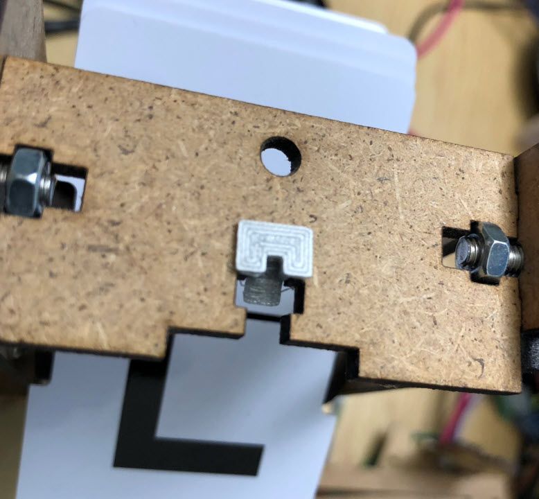
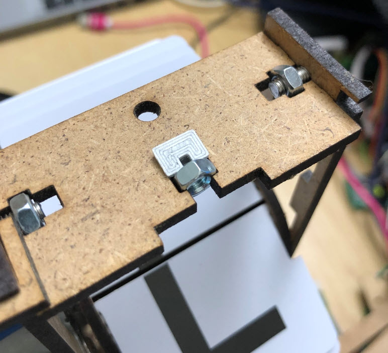
To prevent the front plate nut from falling out the enclosure, it is kept in place with a 3D printed holder:
3D printed holders are used for the electronic boards behind the units. The holder simply get clipped between the enclosure units:
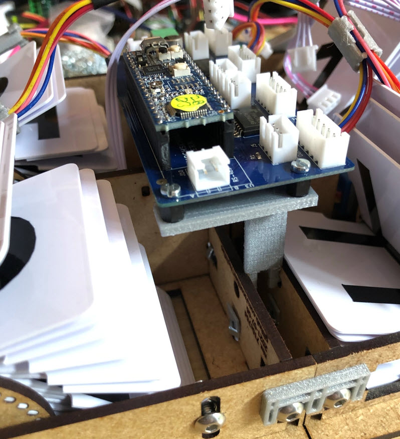
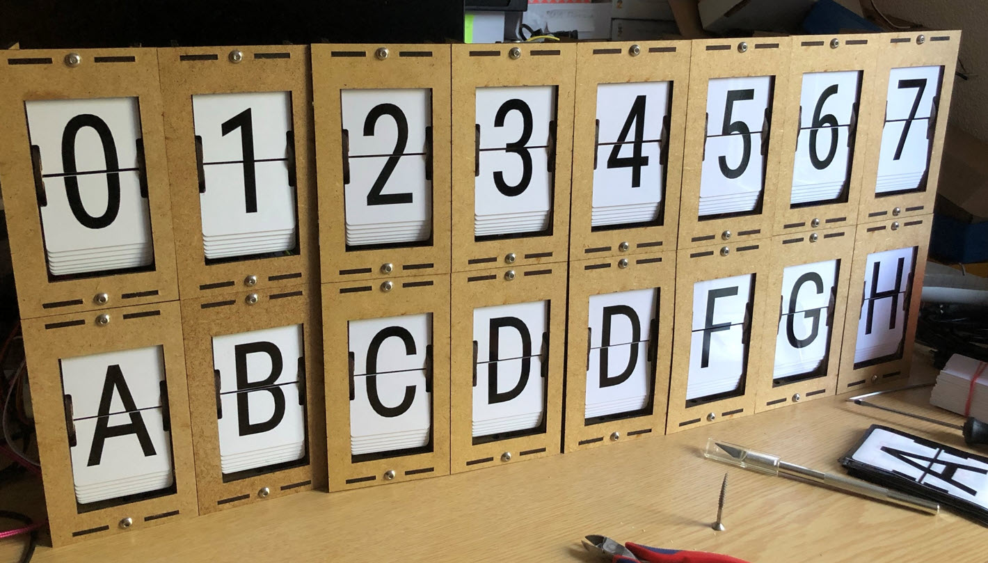
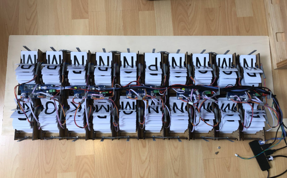
Below the assembly of 20 split-flap units:
To keep the motor cables away from the flaps, I have added a 3D printed cable tunnel:
Flaps
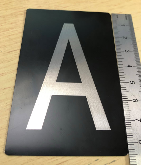
One of the most important part of a split-flap are the flaps. I did experiment with aluminum flaps, but the sound of the flaps was not so good in my opinion.
The advantage would have been that they can be directly engraved with a laser cutter:
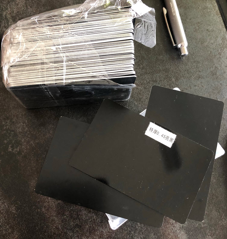
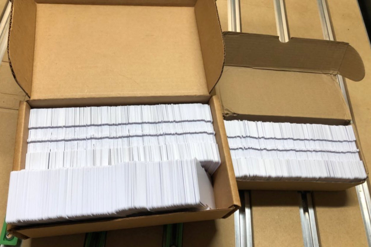
So I ended up using PVC cards, the same kind of material which is used in Scott’s original project: Credit-card-size PVC cards which then can be cut to be used as flaps:
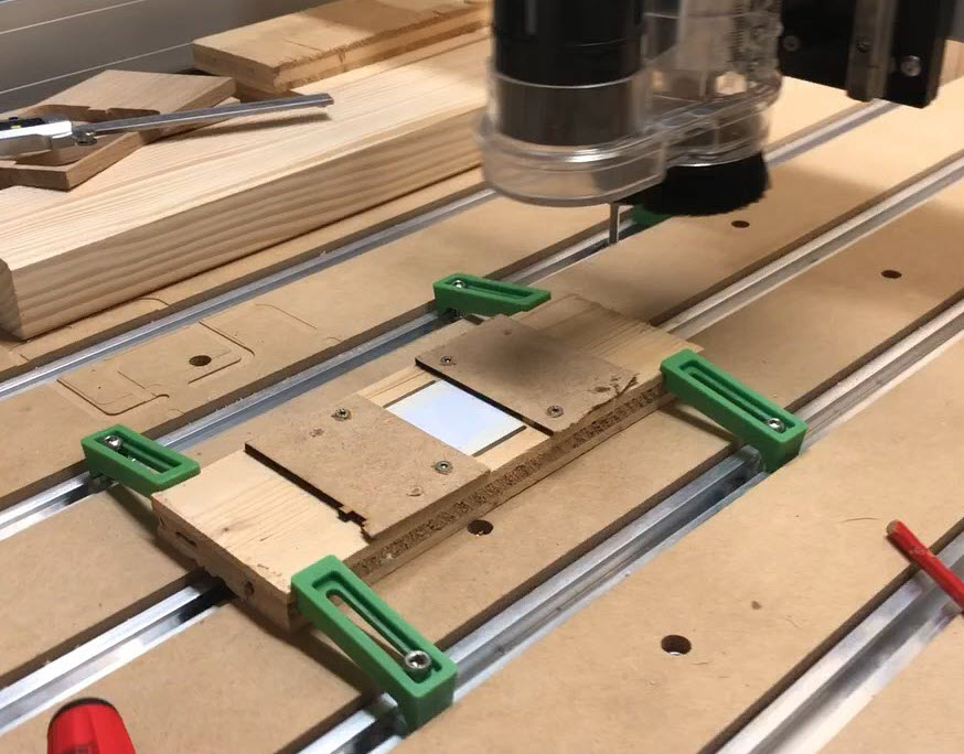
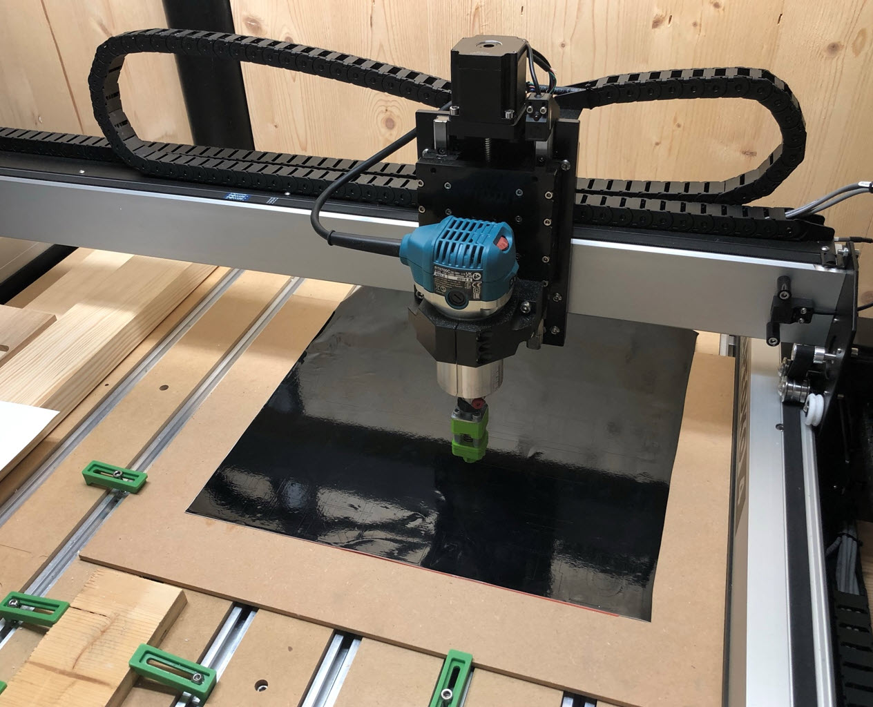
But because of the ‘C’ for chlorine in PVC, it is very dangerous to cut them with a laser cutter. So instead, I used a desktop CNC to cut them.
To cut the flaps with the CNC, I created a jig:
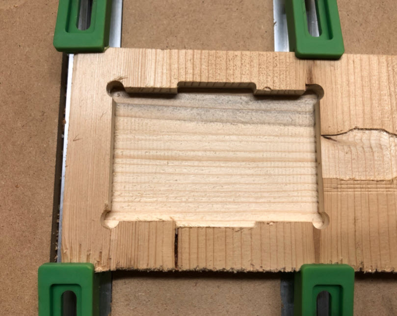
Up to 10 PVC cards can be put into it:
Two pieces of MDF with screws keep them in place:
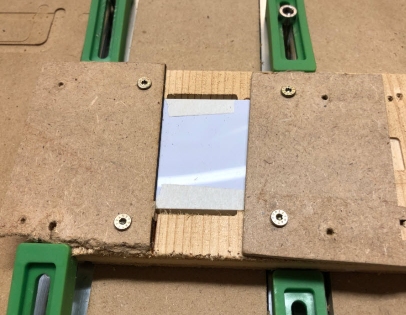
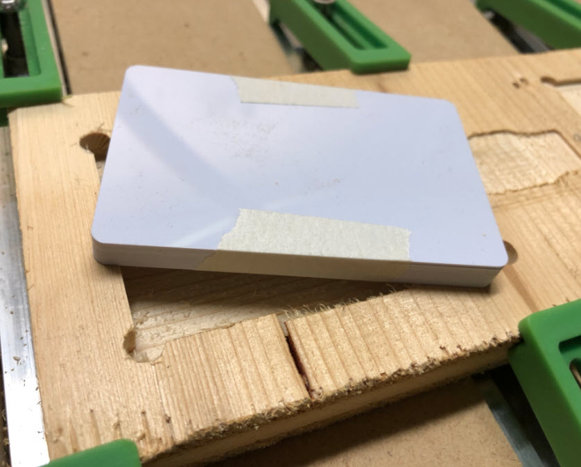
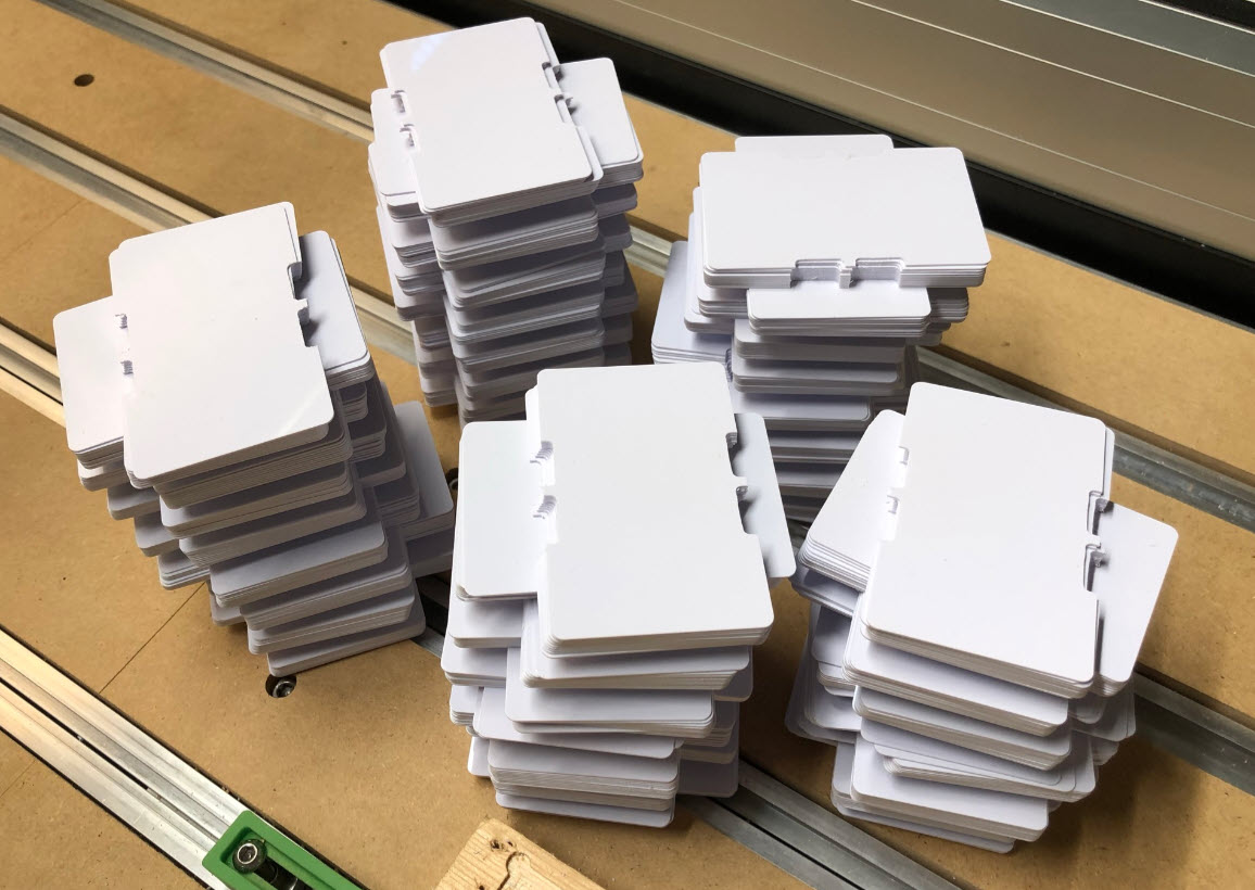
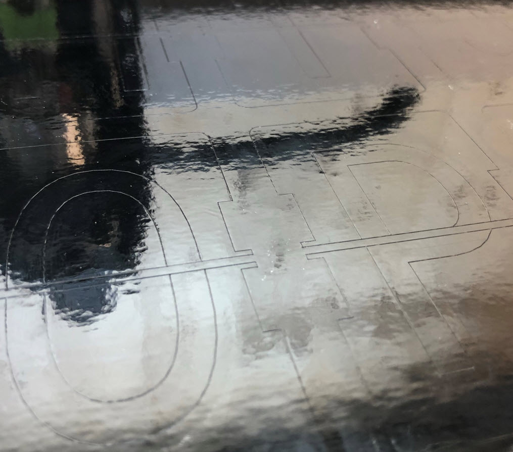
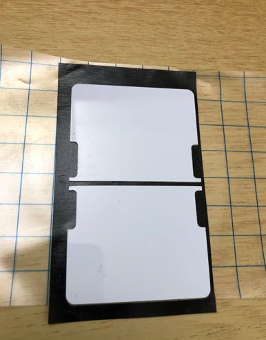
Then the ‘tabs’ get milled out with a 1/8″ end mill. The result are cards with the needed cutouts:
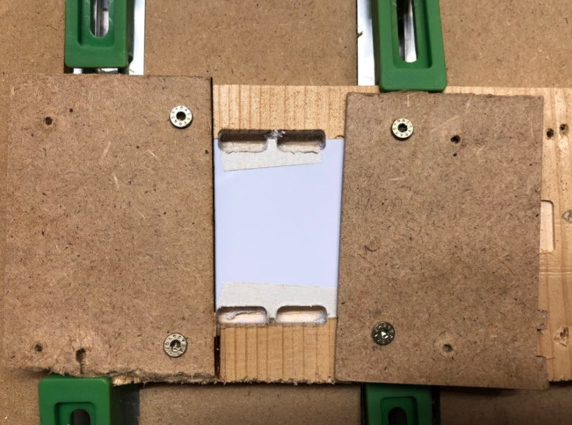
With the masking tape which tightly keeps the cards in place, the result is clean and needs no real post-processing.
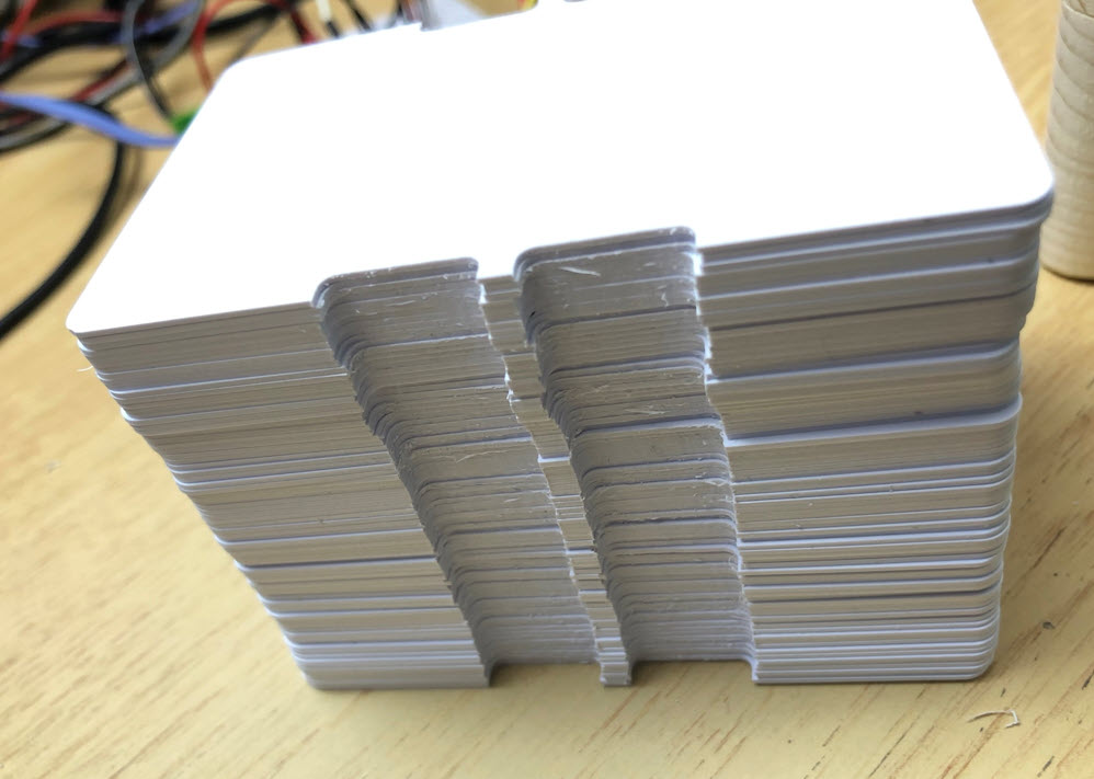
Below some of the cards cut with the CNC:
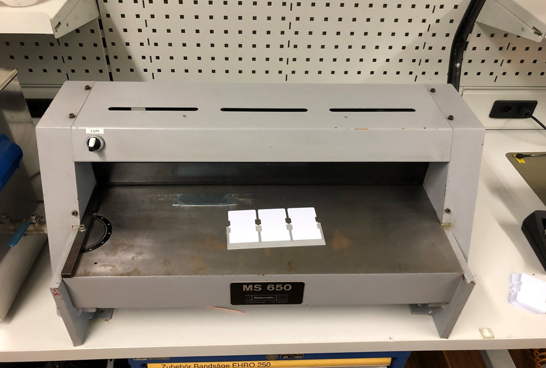
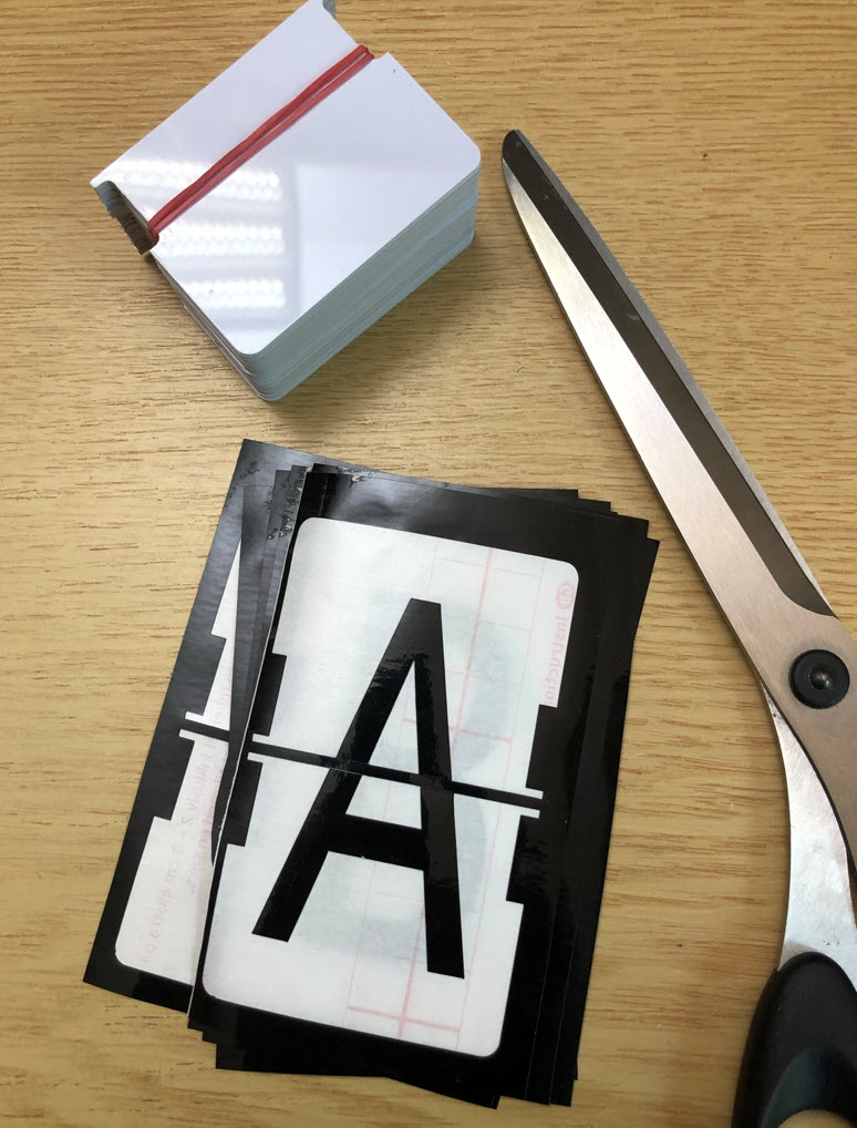
The next step is to cut them in half.
I did consider cutting them with knife or directly with the CNC. The best solution was to use a cutter which is used to cut wood or PCBs. A 3D printed jig is used to cut multiple cards in a single step:
Letters
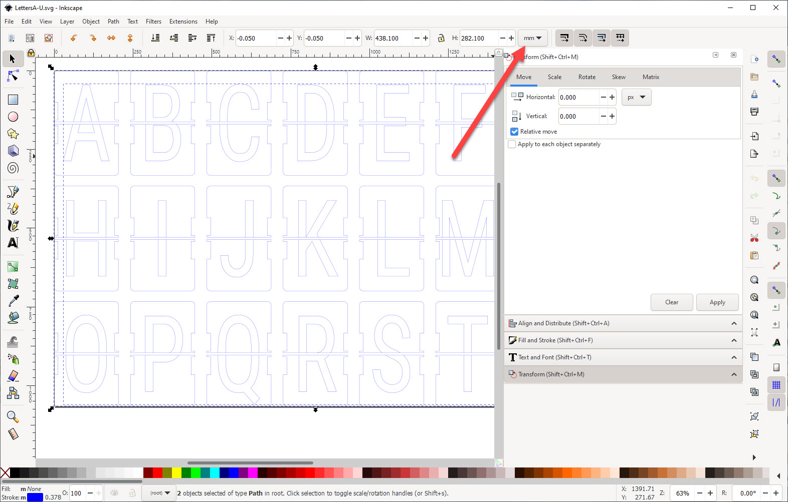
Many thanks to Dave Madison who created python scripts to create split-flap letters, which I used to create all the letters. Below the two lines to create two sets of letters I can cut with the CNC:
python scripts/generate_fonts.py -t "ABCDEFGHIJKLMNOPQRSTU" --ncolumns 7

python scripts/generate_fonts.py -t "VWXYZ0123456789!?+.-#" --ncolumns 7
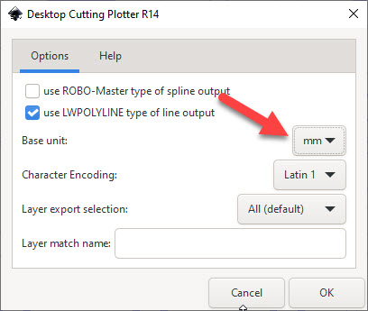
This generates SVG files which can be loaded into Inkscape and then converted into DXF files: Make sure units are set to millimeters:
Then store the file into the .dxf format (File > Save As..). Here again make sure it is using mm:
Then load each file into DXF2GCODE (see “Optimized Vinyl Cutting G-Code Tool Path with DXF2GCODE“) and create the G-Code files. Make sure to set the correct origin with Options > Move Workpiece Zero (I’m using lower left corner):
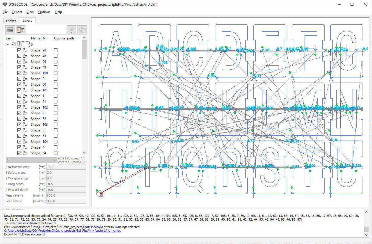
Because I do the tool change manually, I have commented out the M6 (tool change command) in the resulting file(s).
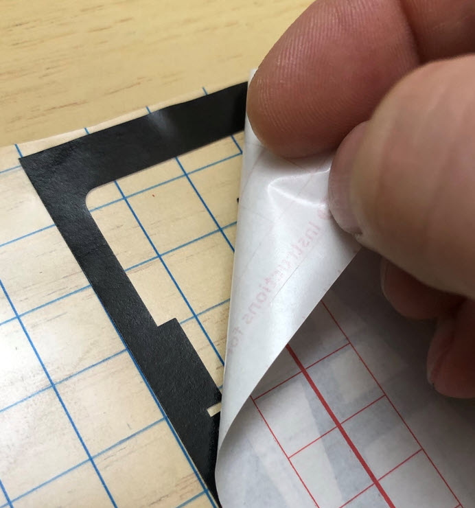
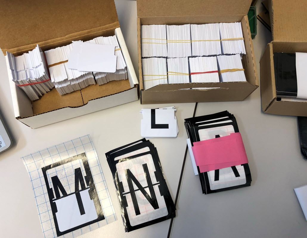
The letters then get applied to the flaps with a transfer foil:


Using the above process, it takes about 20-25 minutes to apply the letters for a single split-flap unit.
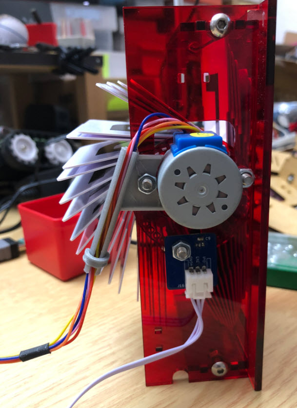
Hardware: Motors, Nuts, …
The motors (28BYI-48) are available in many stores. Make sure it is the 12V version:
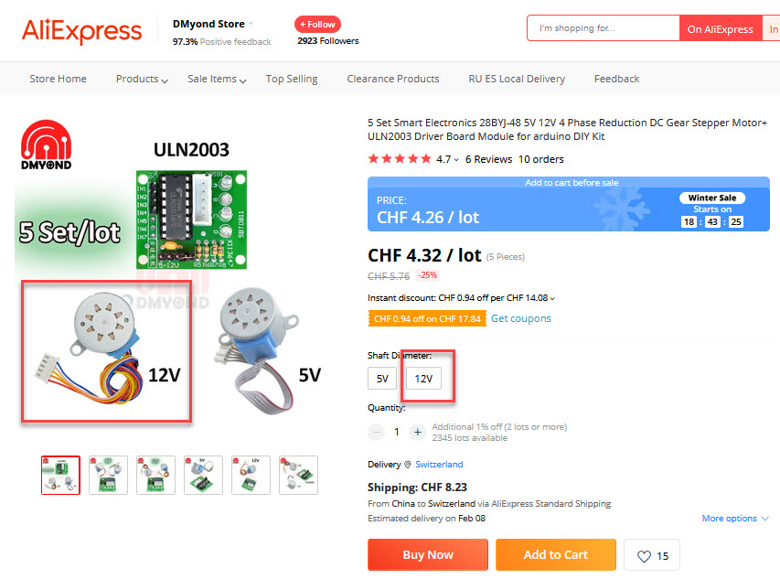
In general for all the hardware (nuts, …), I recommend you follow the guide on Scott’s GitHub Wiki: https://github.com/scottbez1/splitflap
Electronics
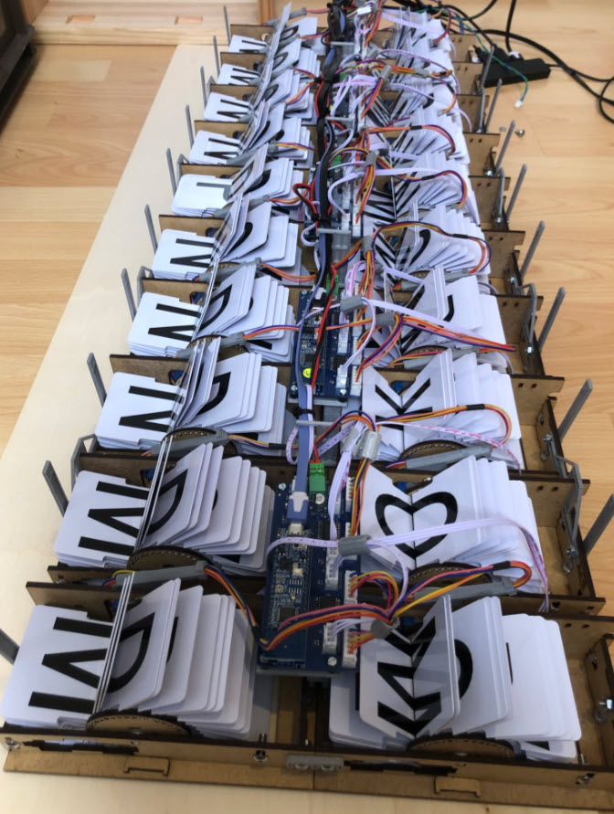
A first proof of concept was pretty messy, but worked :-).
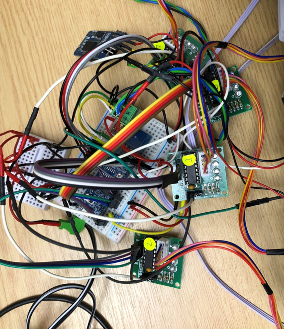
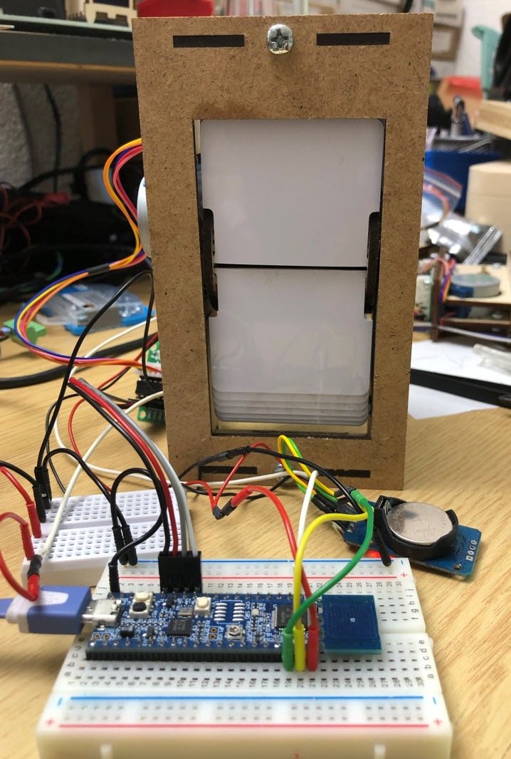
Below a first test with units:
Because these days it is very hard to get microcontroller, and because most students already have a tinyK22 or LPC845-BRK board, two designs around these boards have been created in KiCAD:


The two boards are very similar: the main difference is if a LPC845-BRK (NXP ARM-Cortex M0+) or tinyK22 (NXP ARM-Cortex M4F) is used as MCU board.
- 12V Power supply
- 4 ‘breakable’ sensor PCBs for the hall sensors
- JST 2.5mm connectors
- RS-485 communication interface
- up to 4 split-flaps
- tinyK22 version only: I2C (OLED) connector and UART for ESP32


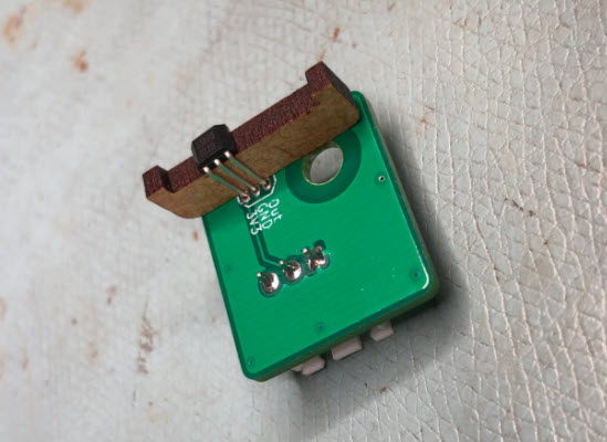
The sensor PCBs get detached from the main PCB.

On the back side, there is the through-hole hall sensor:
Firmware
The firmware is uses FreeRTOS with the McuLib and is runs with the NXP MCUXpresso SDK and IDE:

The firmware includes a command line interface, which can be used with USB-CDC, SEGGER RTT, UART, RS-485 or over WifFi with an attached ESP32. Text over multiple lines can be sent with a ‘\n’, e.g.
will show the text on two lines.

The settings are stored in FLASH memory using key-value pairs. The position of each split-flap unit can be freely configured (x, y position on display).
In case of missed steps of the stepper motors, the firmware is able to detect this with the magnet and hall sensor and automatically corrects it on-the-fly. For easy re-wiring of split-flap units, the firmware includes a pre-configured offset table, reducing the installation or reconfiguration time.
Both the tinyK22 and LPC845-BRK version uses shared firmware sources. For a larger display the boards communicate over the RS-485, and the display content can be controlled from a single controller board, from the Host PC (UART, SEGGER RTT, USB CDC) or over WiFi with an attached ESP32. The tinyK22 boards can use a OLED (SSD1306) display too.
Summary
Currently I have 30 Split-Flap units assembled, with material for about 20 more units, so next step will be to build a larger display. With the RS-485 bus, there is a limit of around 128 devices (4*128 split-flaps) on a single bus, but then the 12V power monitoring and distribution would get more challenging. Currently there is one MCU needed for 4 split-flaps: this is fine for the class environment, but for larger displays an overkill. Scott has been working on a chain-link version: a student just finished a similar project: driving larger displays with just a single MCU. More about this probably in a future article.
I want to thank again Scott Bezek for his work and excellent documentation, which was a big help for this project.
Happy flapping 🙂
Links
- Optimized Vinyl Cutting G-Code Tool Path with DXF2GCODE
- DIY Vinyl Cutting Drag Knife for Desktop CNC
- Jig to cut PVC cards: https://cutrocket.com/p/61055ffd3fbac/
- Building DIY Split-Flap Displays by Dave Madison