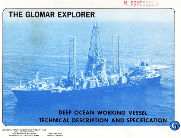
The Glomar Explorer, Deep Ocean Working Vessel, Technical Description and Specification, 1975, describes the Glomar Explorer in the context of her cover story. Search on Glomar Explorer and Project Azorian to learn about her CIA sponsored mission to recover a Soviet submarine. Also see photos inside HMB-1 during 2011. At the bottom of HMB-1 tour there are additional documents describing Project Azorian and Glomar Explorer that readers of this document will want to explore.
In this online version of the manual we have attempted to keep the flavor of the original layout while taking advantage of the Web's universal accessibility. Different browsers and fonts will cause the text to move, but the text will remain roughly where it is in the original manual. In addition to errors we have attempted to preserve from the original this text was captured by optical character recognition. This process creates errors that are compounded while encoding for the Web.
Please report any typos, or particularly annoying layout issues with the Mail Feedback Form for correction.
Richard Pekelney
Webmaster
|
CAUTIONARY NOTICE This document, "The Glomar Explorer Deep Ocean Working Vessel - Technical Description and Specification," either discloses in part or touches upon certain technical information, developments and innovations which are regarded by Global Marine Development Inc. to be PROPRIETARY to it and to its related companies and associates. Global Marine Development Inc. strives to respect the proprietary interests of others, and believes that others owe it the same respect. Therefore, no portion of the information or data contained herein may be reproduced, in whole or in part, in any manner or used for manufacture or other purposes, public or otherwise, unless the written consent of Global Marine Development Inc. has first been obtained pursuant to a formal request which shall 1) identify the portion hereof | ||||||||||||||||||||||||||||||||||||||||||
|
| ||||||||||||||||||||||||||||||||||||||||||
|
CAUTIONARY NOTICE desired to be reproduced or used and 2) state the purpose for which such re- production or use is desired. Certain of the technical developments described herein are the subject of pending or issued patents in the United States and in other countries. The patents issued include but are not limited to United States Patents 3,894,640, 3,918,379 and 3,918,380. | ||||||||||||||||||||||||||||||||||||||||||
|
i | ||||||||||||||||||||||||||||||||||||||||||
|
TABLE OF CONTENTS
| ||||||||||||||||||||||||||||||||||||||||||
|
ii | ||||||||||||||||||||||||||||||||||||||||||
|
TABLE OF CONTENTS (Continued)
| ||||||||||||||||||||||||||||||||||||||||||
|
iii | ||||||||||||||||||||||||||||||||||||||||||
|
LIST OF ILLUSTRATIONS
| ||||||||||||||||||||||||||||||||||||||||||
|
iv | ||||||||||||||||||||||||||||||||||||||||||
|
LIST OF ILLUSTRATIONS (Continued)
| ||||||||||||||||||||||||||||||||||||||||||
|
v | ||||||||||||||||||||||||||||||||||||||||||
|
LIST OF ILLUSTRATIONS (Continued)
| ||||||||||||||||||||||||||||||||||||||||||
|
vi | ||||||||||||||||||||||||||||||||||||||||||
|
LIST OF ILLUSTRATIONS (Continued)
| ||||||||||||||||||||||||||||||||||||||||||
|
vii | ||||||||||||||||||||||||||||||||||||||||||
|
LIST OF ILLUSTRATIONS (Continued)
| ||||||||||||||||||||||||||||||||||||||||||
|
viii | ||||||||||||||||||||||||||||||||||||||||||
|
LIST OF TABLES
| ||||||||||||||||||||||||||||||||||||||||||
|
1 | ||||||||||||||||||||||||||||||||||||||||||
|
STATEMENT OF PURPOSE This brochure is intended to provide an introductory technical description of the GLOMAR EXPLORER, a unique deep ocean working vessel. This unusual ship incorporates many innovative engineering features which are significant advances beyond the present state of the art. A limited distribution of this brochure is being made to acquaint interested persons with details of this technology. It is hoped that making others aware of the GLOMAR EXPLORER's capability to perform work in the marine environment heretofore considered impossible will stimulate those with imaginative and far reaching ideas to make use of this capability. The Global Marine Development Inc. engineering design and systems management team brought the GLOMAR EXPLORER from concept to drawing board, and through construction to its first deep water operation in 29 months, a record time. | ||||||||||||||||||||||||||||||||||||||||||
|
2 | ||||||||||||||||||||||||||||||||||||||||||
|
Global Marine Development Inc. would welcome inquiries or proposals from interested parties on possible applications of the GLOMAR EXPLORER's systems' technology.
Global Marine Development Inc. does not own the GLOMAR EXPLORER nor any of its subsystems, and therefore cannot guarantee the availability of said vessel nor of its subsystems. The purpose of this brochure is to demonstrate the technical capabilities and competence of Global Marine Development Inc. to design, develop, and fabricate a system encompassing the GLOMAR EXPLORER's capabilities. | ||||||||||||||||||||||||||||||||||||||||||
|
3 | ||||||||||||||||||||||||||||||||||||||||||
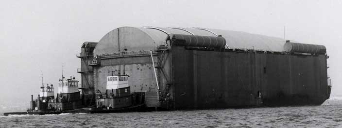
HMB-1 with Tugs
|
5 | ||||||||||||||||||||||||||||
|
| ||||||||||||||||||||||||||||
|
| ||||||||||||||||||||||||||||
| SECTION I - INTRODUCTION | ||||||||||||||||||||||||||||
|
1-1 | ||||||||||||||||||||||||||||
|
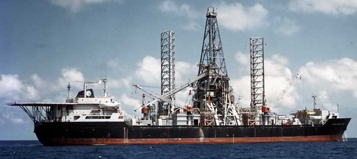
SECTION 1 - INTRODUCTION The twin screw, diesel-electric powered GLOMAR EXPLORER is a ship-shaped vessel with an exceptional number of innovative technical features (see Table 1-1). The first of its kind, the ship was specially designed by Global Marine Development Inc. to dynamically maintain its position over a work site as deep as 17,000 feet while lowering or raising heavy subsea equipment or operating this equipment on the bottom. The ship is capable of carrying 25,000 tons of equipment, consumables, and stores, sufficient to allow a 100-day voyage without resupply. Figure 1-1 shows the general arrangement of the GLOMAR EXPLORER. Tables 1-2 and 1-3 give general characteristics and principal dimensions; Table 1-4 outlines cargo capacities; and Table 1-5 indicates system performance characteristics. Miscellaneous equipment contained on board is listed in Table 1-6. | ||||||||||||||||||||||||||||
|
1-2 | ||||||||||||||||||||||||||||
The ship meets or exceeds the applicable rules of the American Bureau of Shipping and is classed  . In addition, the ship complies with the applicable requirements of governmental regulatory bodies, such as the U.S. Coast Guard, Federal Communications Commission, and U.S. Public Health Service. . In addition, the ship complies with the applicable requirements of governmental regulatory bodies, such as the U.S. Coast Guard, Federal Communications Commission, and U.S. Public Health Service.
| ||||||||||||||||||||||||||||
|
1-3 | ||||||||||||||||||||||||||||
|
Figure 1-1. General Arrangement of Glomar Explorer (1 of 2) Profile Large image on a separate page. | ||||||||||||||||||||||||||||
|
1-4 | ||||||||||||||||||||||||||||
|
Figure 1-1. General Arrangement of Glomar Explorer (2 of 2) Main Deck Arrangement Large image on a separate page. | ||||||||||||||||||||||||||||
|
1-5 | ||||||||||||||||||||||||||||
|
TABLE 1-1. INNOVATIVE TECHNICAL FEATURES
| ||||||||||||||||||||||||||||
|
1-6 | ||||||||||||||||||||||||||||
|
TABLE 1-1. INNOVATIVE TECHNICAL FEATURES (CONTINUED)
| ||||||||||||||||||||||||||||
|
1-7 | ||||||||||||||||||||||||||||
|
TABLE 1-2. GENERAL CHARACTERISTICS
| ||||||||||||||||||||||||||||
|
1-8 | ||||||||||||||||||||||||||||
|
TABLE 1-3. PRINCIPAL CHARACTERISTICS DIMENSIONS AND DISPLACEMENTS
| ||||||||||||||||||||||||||||
|
1-9 | ||||||||||||||||||||||||||||
|
TABLE 1-3. PRINCIPAL CHARACTERISTICS (CONTINUED) MACHINERY
PROPELLERS
ANCHORS
| ||||||||||||||||||||||||||||
|
1-10 | ||||||||||||||||||||||||||||
|
TABLE 1-4. CARGO CAPACITY
| ||||||||||||||||||||||||||||
|
1-11 | ||||||||||||||||||||||||||||
|
TABLE 1-4. CARGO CAPACITY (CONTINUED)
| ||||||||||||||||||||||||||||
|
1-12 | ||||||||||||||||||||||||||||
|
TABLE 1-5. DESIGN AND OPERATING SPECIFICATIONS I. UNDERWAY
II. DOCKING
| ||||||||||||||||||||||||||||
|
1-13 | ||||||||||||||||||||||||||||
|
TABLE 1-5. DESIGN AND OPERATING SPECIFICATIONS (CONTINUED)
III. OPERATING
| ||||||||||||||||||||||||||||
|
1-14 | ||||||||||||||||||||||||||||
|
TABLE 1-5. DESIGN AND OPERATING SPECIFICATIONS (CONTINUED)
| ||||||||||||||||||||||||||||
|
1-15 | ||||||||||||||||||||||||||||
|
TABLE 1-5. DESIGN AND OPERATING SPECIFICATIONS (CONTINUED)
IV. STATIC HOLD - LOAD PLACED ON "PARKING BRAKE"
| ||||||||||||||||||||||||||||
|
1-16 | ||||||||||||||||||||||||||||
|
TABLE 1-6. MISCELLANEOUS EQUIPMENT
| ||||||||||||||||||||||||||||
|
1-17 | ||||||||||||||||||||||||||||
|
TABLE 1-6. MISCELLANEOUS EQUIPMENT (CONTINUED)
| ||||||||||||||||||||||||||||
|
| ||||||||||||||||||||||||||||
|
SECTION II - UNIQUE FEATURES | ||||||||||||||||||||||||||||
|
2-1 | ||||||||||||||||||||||||||||
|
SECTION 2 - UNIQUE FEATURES The most unique features of the GLOMAR EXPLORER are the large center well and gates, which form a dry dock for the subsea equipment; the gimbal system and hydraulic-pneumatic heave compensation system, which provide a stable platform from which the heavy lift pipe is handled; the transverse A-frame which spans the well, supports the gimbal structure, and distributes the heavy lift load into the hull; the pipe handling systems (below deck, above deck, and heavy lift system); and the Le Tourneau docking legs which handle the subsea equipment when in close proximity to the hull. The GLOMAR EXPLORER'S rated heavy lift capacity of 14.0 million pounds, at a continuous speed of 6 ft/min, had a large impact on the vessel's design. Machinery, structures, hull strength, and stability all are affected by this load. Tensile stresses in the heavy lift pipe leave little margin for dynamic or bending stresses due to ship's roll, pitch and heave, thus necessitating the gimballed stable | ||||||||||||||||||||||||||||
|
2-2 | ||||||||||||||||||||||||||||
|
platform. The stable platform requires structure and machinery of its own, all of which is mounted across and above the center docking well. The resulting total load, high above the center of the ship, drastically changes the ship's stability and motion characteristics as well as the hull girder loading. Enough beam and ballast capacity has been provided to maintain at least the minimum amount of stability required by the U.S. Coast Guard.
Mass distribution is such that roll motions are minimal. American Bureau of Shipping high strength steel has been used where required to provide high strength with minimum weight penalty, and extends longitudinally in the hull girder from several frames forward of the docking well to several frames aft of it. A large, unassigned space (14,000 ft3) below decks forward of the well is also available. This space could be utilized for placing laboratory vans, conference rooms, storage, etc., as required. | ||||||||||||||||||||||||||||
|
2-3 | ||||||||||||||||||||||||||||
|
2.1 COVERED CENTER WELL AND GATES
One of the most unique features of the GLOMAR EXPLORER is the large (199 ft long x 74 ft wide x 65 ft high), dry center well. This well, which is totally enclosed, serves as a dry dock for the subsea equipment to be lowered on the pipe string. The size and general arrangement of this well are depicted in Figures 2-1 and 2-2. The well is closed from the sea by two gates which roll longitudinally, one forward and one aft in gate guide rails. Buoyancy of the gates is controlled by regulating air volume in free flooding, saltwater ballast tanks. When the gates are closed and made buoyant, a two-compound rubber gasket between the gate and the ship's bottom shell seals against leakage into the well. The gates are operated by a rack and pinion mechanism, and are made slightly negatively buoyant when being opened or closed. The racks run along the centerline of the gates, and the pinions, located in the fore and aft cofferdams, are chain driven by a hydraulic motor with an intermediate air clutch to accommodate surge | ||||||||||||||||||||||||||||
|
2-4 |
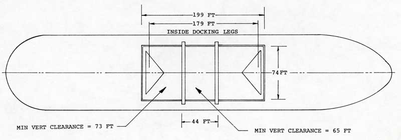
Figure 2-1. Well Envelope
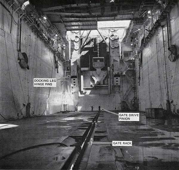
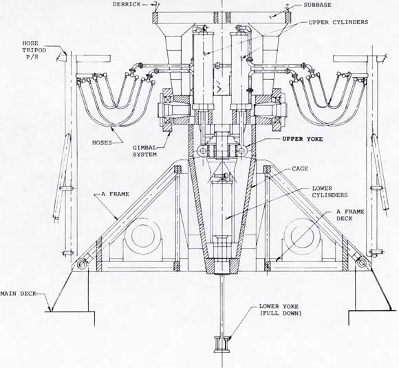
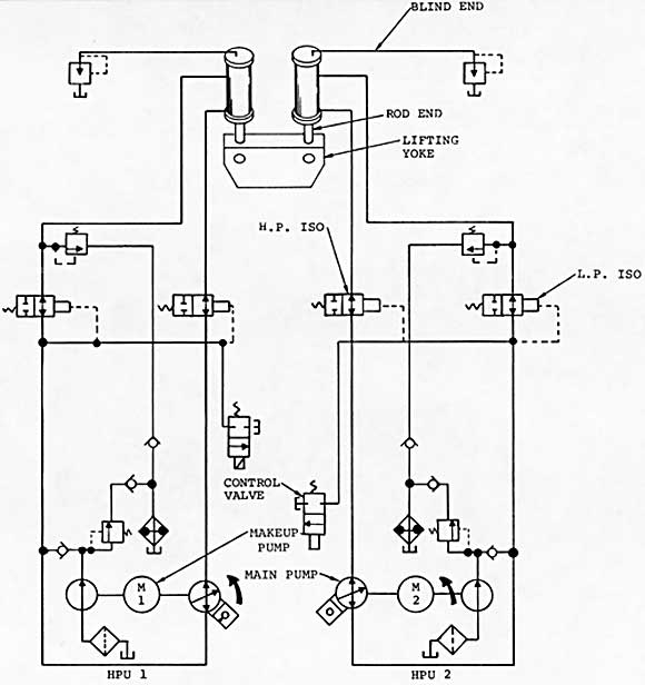
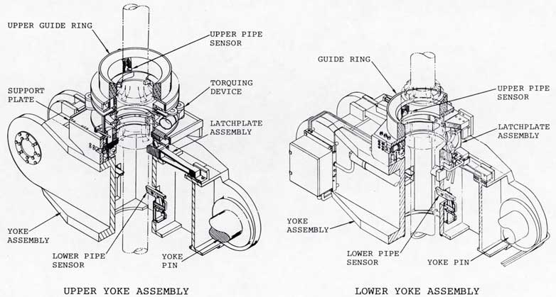
Figure 2-6. Upper and Lower Yoke Assemblies
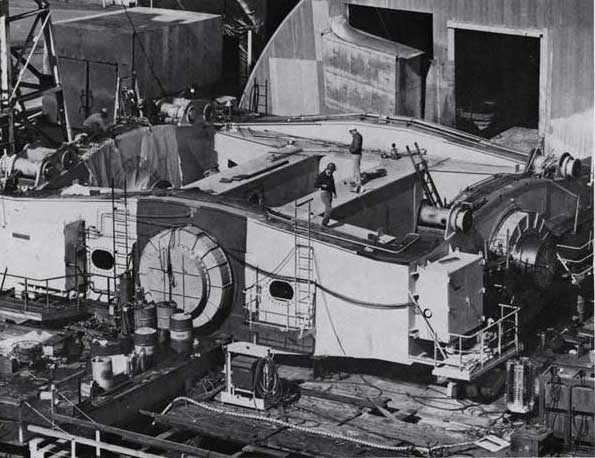
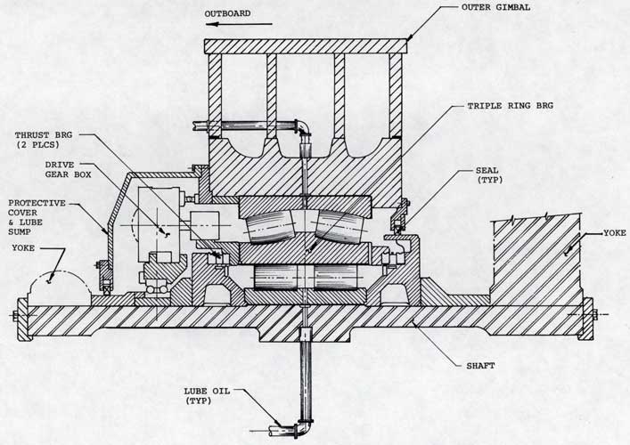
Figure 2-10. Typical Gimbal Roll Axis Bearing Installation
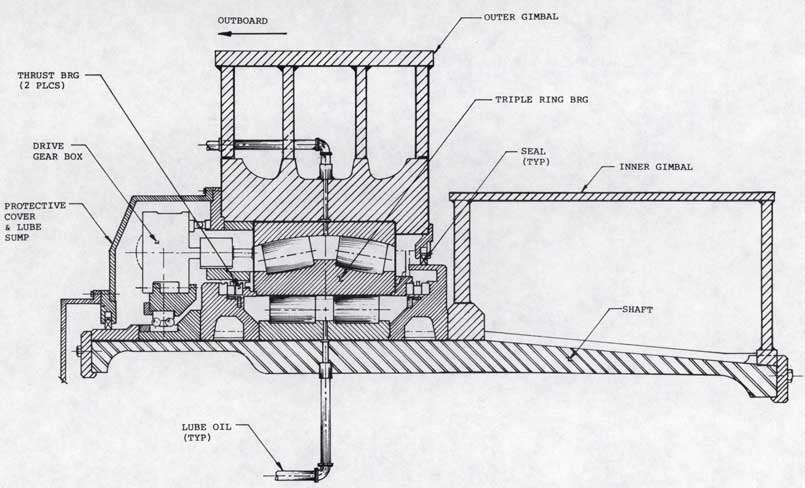
Figure 2-11. Typical Gimbal Pitch Axis Bearing Installation
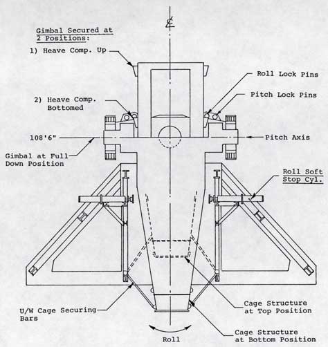
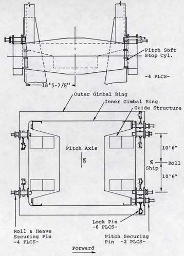
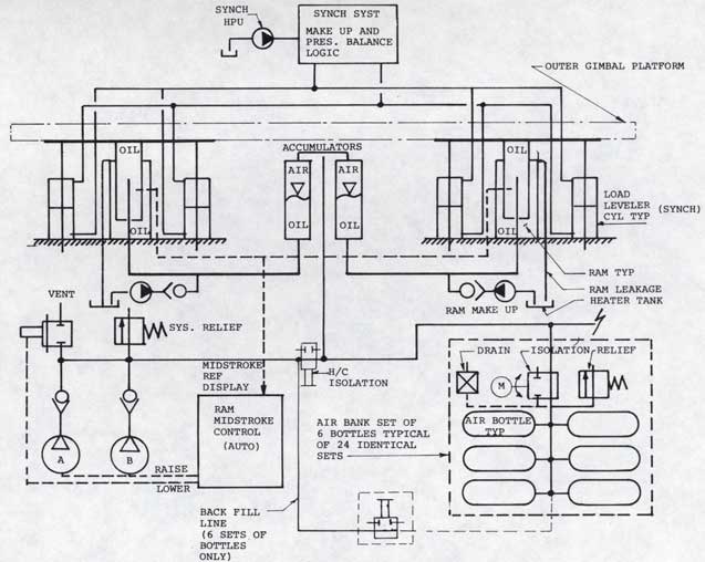
Figure 2-16. Heave Compensation System Schematic
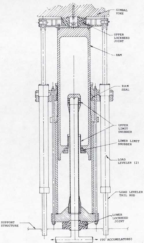
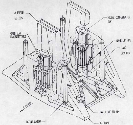
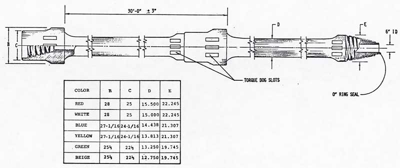
Figure 2-19. Composite Pipe Assembly
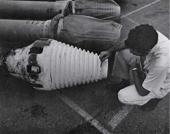
Figure 2-20. View of Pipe Pin End Showing Threads and Torque Slots
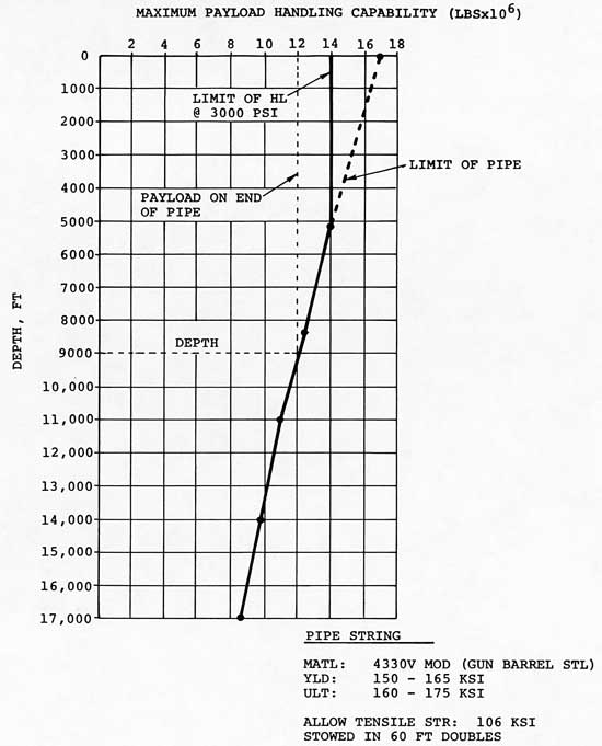
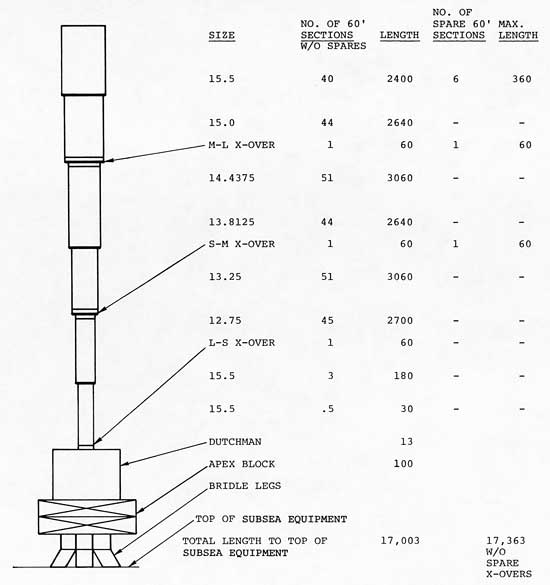
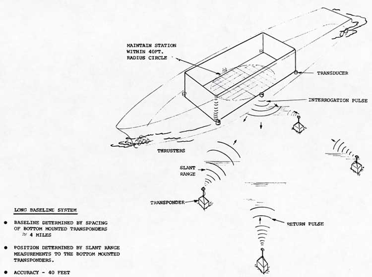
Figure 2-23.Long Baseline System (LBS)
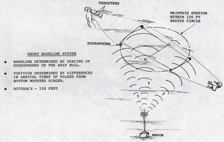
Figure 2-24.SBS Operation
|
2-39 |
|
|
|
2-40 |
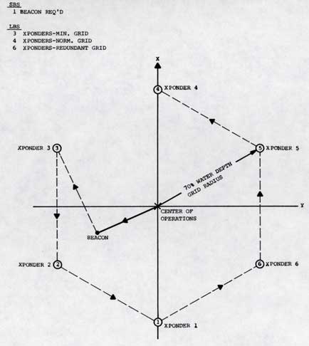
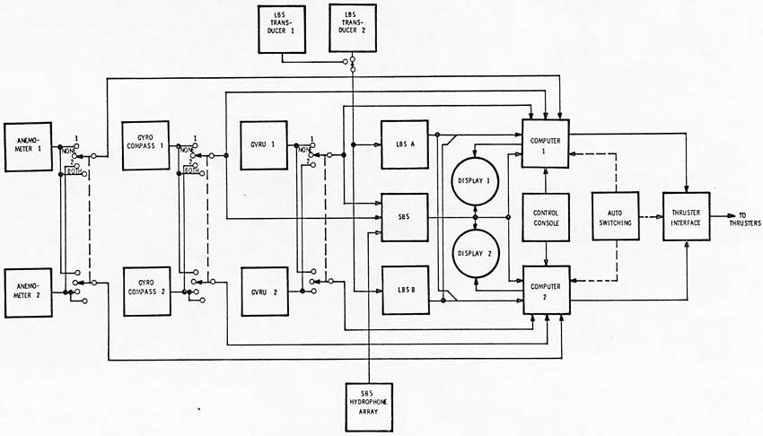
Figure 2-26. ASK System Simplified Block Diagram
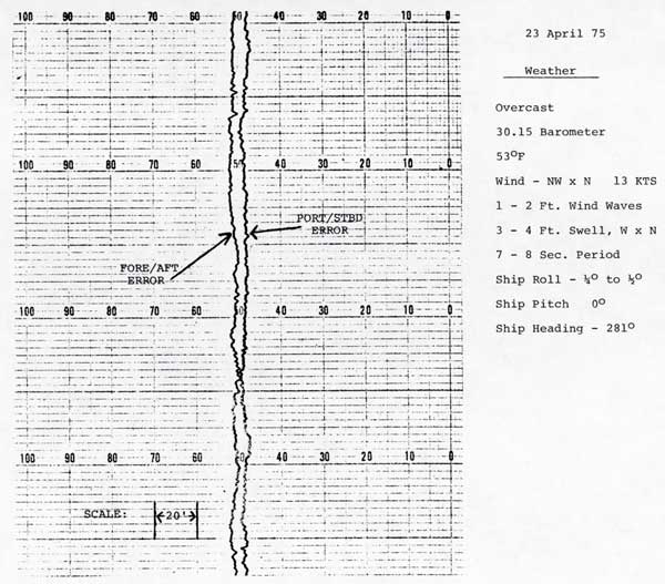
Figure 2-27. LBS Operation, Ship's Position Error
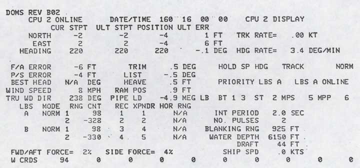
Figure 2-28. ASK/Ship's Systems Status Display
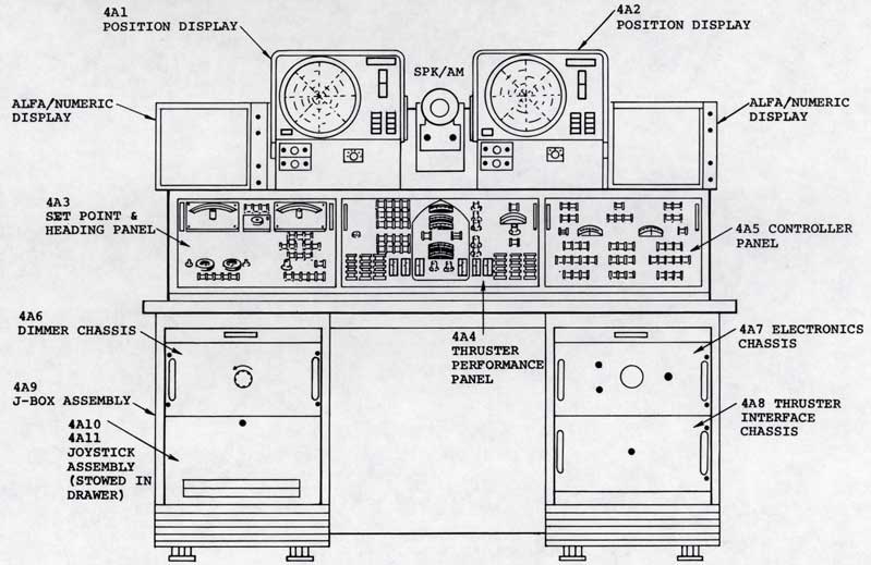
Figure 2-29. ASK Control Console
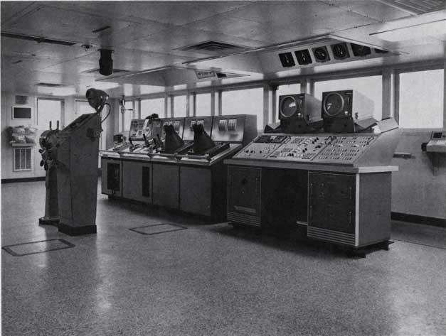
Figure 2-30. Aft Bridge, ASK Console
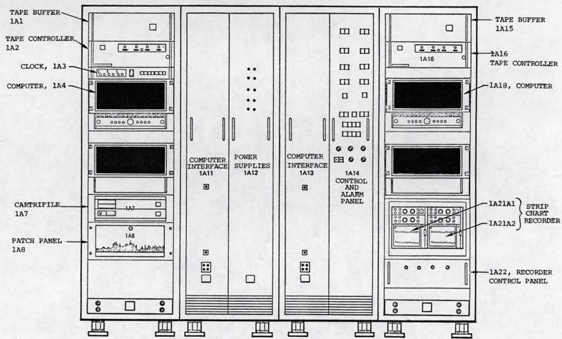
Figure 2-31. ASK Unit Cabinet 1
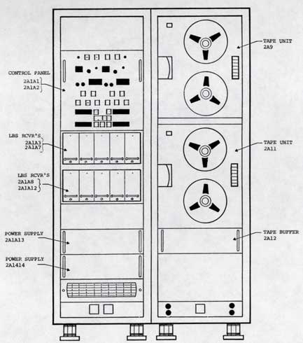
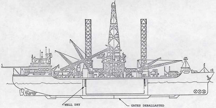
Figure 2-33. Condition on Arrival at Work Area
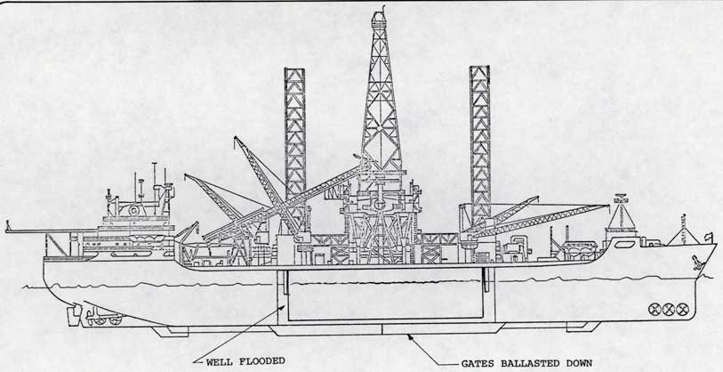
Figure 2-34. Well Flooded - Gates Ballasted
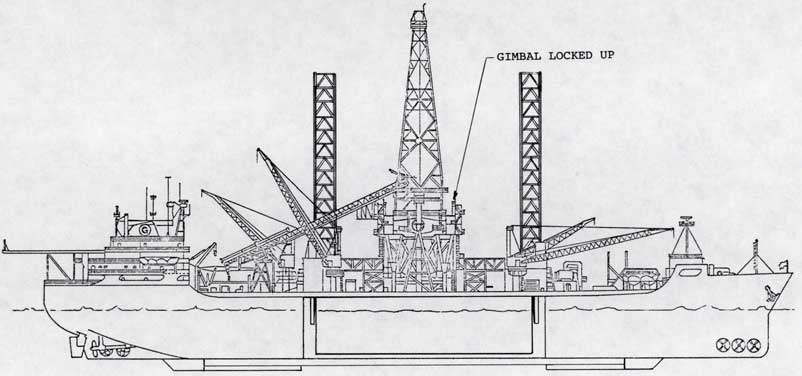
Figure 2-35. Gates Opened and Deballasted
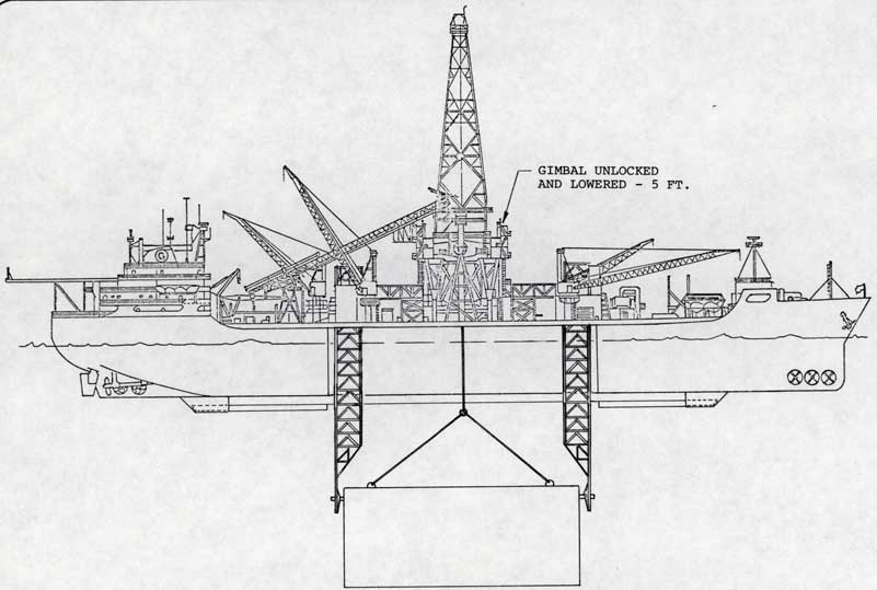
Figure 2-36. Subsea Equipment Lowered to Release Depth
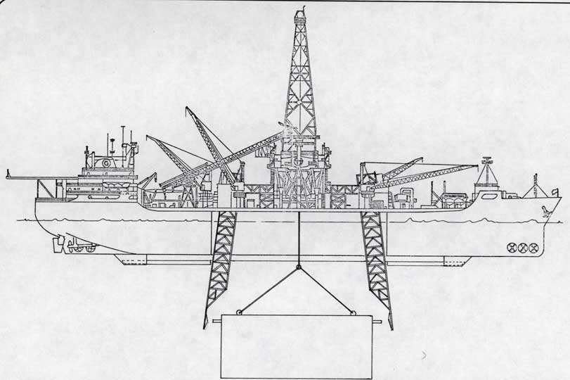
Figure 2-37. Subsea Equipment Undocked and Ready for Lowering
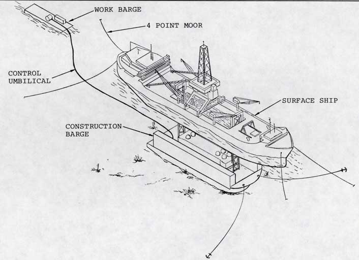
Figure 2-38. Mate/Demate Configuration
|
2-61 |
|
|
|
2-62 |
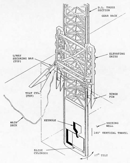
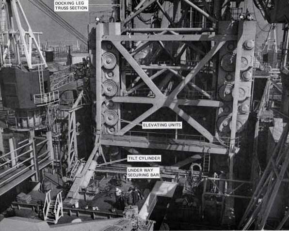
Figure 2-39. Docking Leg System (2 of 3)
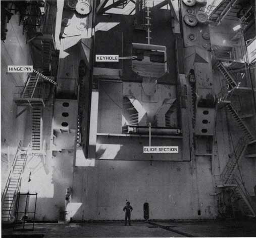
Figure 2-39. Docking Lea System (3 of 3)
|
2-64 | ||||||||||||||||||
|
portion to allow lateral shifting of the supported equipment. This allows storage of unsymmetrical equipment in the well. A continuous rack runs up the entire length of both sides of the leg. The legs are raised/lowered by electric powered elevating units on either side of each leg. The elevating units are interconnected by a truss work and supported on hinge pin attachments to the cofferdam at either end of the well. While the legs are fully elevated they are locked in place with locking bars. During undocking, after the legs have been lowered to a certain depth, these locking bars are disconnected. The legs are then controlled in tilt by the large tilt cylinders (2 on each leg). In addition to providing a means of tilting the legs in or out, these cylinders also have integral hydraulic manifolds with snubbing valves to dampen "swinging" motions of the legs induced by ship pitching.
The load capabilities of the docking leg system under various operating conditions are summarized in Table 2-1. | ||||||||||||||||||
|
2-65 | ||||||||||||||||||
|
TABLE 2-1.DOCKING LEG SYSTEM DESIGN CRITERIA
I. LOADS
1. Operating
| ||||||||||||||||||
|
2-66 | ||||||||||||||||||
|
TABLE 2-1. DOCKING LEG SYSTEM DESIGN CRITERIA (CONTINUED)
2. Impact Loads During Docking
II. RELATIVE MOTION DURING DOCKING (BETWEEN LEG AND SUBSEA EQUIPMENT)
| ||||||||||||||||||
|
2-67 | ||||||||||||||||||
|
TABLE 2-1. DOCKING LEG SYSTEM DESIGN CRITERIA (CONTINUED) III. GEOMETRIC REQUIREMENTS
| ||||||||||||||||||
|
2-68 | ||||||||||||||||||
|
2.8 SEMI-AUTOMATIC PIPE HANDLING SYSTEM
The pipe handling system is designed to transport the heavy lift pipe from the pipe storage hold, aft of the docking well, to a vertical position in the derrick for sequential assembly into the pipe string (or the reverse sequence). This system consists of the following seven major subsystems (see Figures 2-40 and 2-41).
| ||||||||||||||||||
|
2-69 | ||||||||||||||||||
|
| ||||||||||||||||||
|
2-70 | ||||||||||||||||||
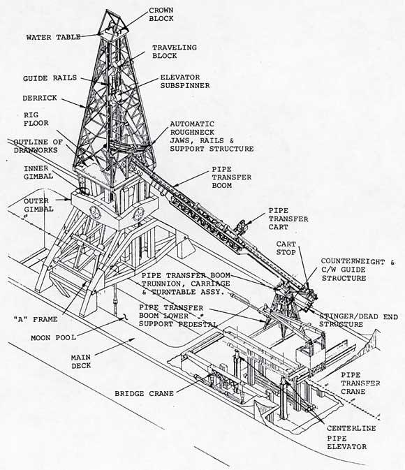
Figure 2-41. Pipe Handling System, Above Deck (1 of 2)
Figure 2-41. Pipe Handling System, Above Deck (2 of 2)
|
2-72 |
|
The major requirement of the overall system is the capability to deliver or receive a 40,000 pound, 60 foot long heavy lift pipe every 10 minutes continuously under ± 3 1/2 degrees roll, ± 3 degrees pitch and ± 5 feet heave ship operating conditions.
The bridge cranes transfer the heavy lift pipe in the pipe storage hold between the storage bays and the centerline elevator trunks (see Figure 2-42). The bridge cranes also place and remove the sleepers from the bays to the sleeper stowage areas at the fore and aft ends of the hold. There are two bridge cranes, one port and one starboard. Each can service five of the six bays and the centerline elevator. The electric powered, rack and pinion drive is mounted overhead of the stowed pipe on transverse rails. Monorail cranes on the fore and aft end of the bridge cranes handle the pipe sleepers. The centerline elevator lifts or lowers the heavy lift pipe between the elevator trunks and a position five feet above the main deck level. The elevators consist |
|
2-73 |
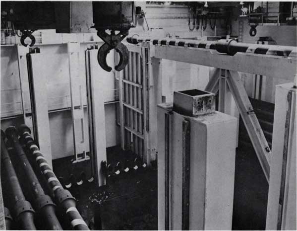
Figure 2-42. Pipe Handling System, Below Deck
|
2-74 |
|
of two - 250 1/4 inch stroke, double-acting hydraulic cylinders, guided with telescoping guides.
The transfer crane delivers or receives pipe from the centerline elevator in its elevated position five feet above the main deck to the transfer boom cart. The crane is powered by a diesel engine driving multiple hydraulic pumps. The control system is an electro-mechanical semi-automatic or completely manual system. This crane is driven transversely by a rack and pinion drive. The crane boom tilt is powered by a hydraulic cylinder. The pipe grapple drive screws are actuated by a hydraulic motor. This unit is rotated and tilted with hydraulic cylinders for pipe positioning. The transfer boom system transfers the heavy lift pipe from main deck starboard to the gimballed rig floor. The lower section of the pipe transfer boom is supported on a gimbal which also allows the boom to translate fore and aft. The upper end of the boom is pinned to and supported above the rig floor. |
|
2-75 |
|
The pipe is transported upon a cart which rides the boom and is raised and lowered by a cable and hydraulic hoist mounted at the upper end of the boom. This system is controlled semi-automatically by an operator on the rig floor.
The derrick pipe handling system consists of two major subsystems: 1. The automatic roughneck - This device handles the lower end of the pipe from the transfer cart to the well centerline. This unit is controlled by the operator who is also controlling the transfer system. 2. The elevator-subspinner - This device is hooked below the traveling block and handles the upper end of the heavy lift pipe. It also provides sub-torquing of the pipe into the string (see Figure 2-43). |
|
2-76 |
|
|
|
2-77 |
|
2.9 POSITIONABLE UNDERWATER WORK PLATFORM
It is possible to lower a large positionable underwater work platform from the GLOMAR EXPLORER. Figure 2-44 depicts such a platform which has the capability to maintain position within ± 2 1/2 feet in surge, sway and heave (Sea States 4 and 5). The platform is suspended from the pipe string on a three-legged bridle and is connected to the pipe through a pinned joint. Power to the platform is provided via the two EM cables and seawater hydraulics system supplied from the surface vessel. Maneuvering or positioning is maintained with the eight large seawater powered thrusters. Two smaller electric yaw thrusters supply fine control. The eight pressure spheres contain the control logic. The two large pins at either end of the platform are used to capture and support the system with the docking legs. |
|
2-78 |
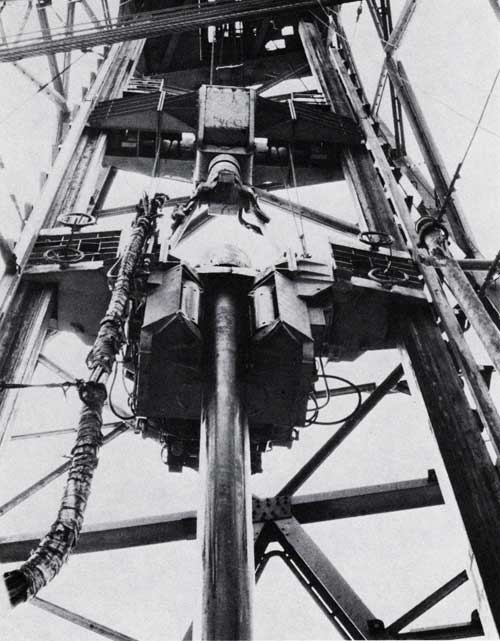
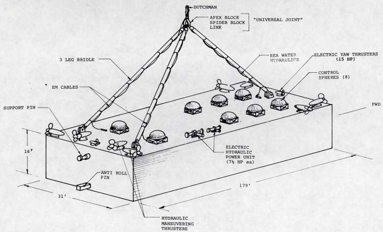
Figure 2-44. Positionable Underwater Work Platform
|
2-79 |
|
2.10 MAIN POWER SYSTEM
This ship is basically a diesel electric vessel. Primary power is generated by five diesel generator sets which provide power to a common AC power bus. Each generator is capable of developing 4375 KVA of three phase power at 4160 V, 60 HZ with a 0.8 power factor. This power is then distributed directly as 4160 VAC or is stepped down to 480 VAC and distributed through any of three major motor control centers. 120/208 VAC power is also provided via transformers and multiple distribution panels for lighting and other small electrical loads. Static converters are used to provide controllable DC power for use with the propulsion motors, thrusters, and subsea equipment. Many of the sophisticated electronic loads used aboard the GLOMAR EXPLORER require highly regulated clean "power". A series of ride-through (flywheel coupled motor-generator sets) power supplies are provided to accommodate these power requirements. |
|
2-80 |
|
In the event the main power plant drops off the line, an emergency diesel-generator set is provided. The diesel automatically starts on loss of main plant power and the emergency generator is automatically connected to the emergency power distribution switchboard.
Monitoring of the power generation and distribution system is performed from the Engineer's Control Room located in the main switchboard room. Control of the diesel-generator and various power distribution assignments are also made from the control center. The entire generation and distribution system has been built to meet or exceed USCG-259, IEEE-45, and ABS Rules and Regulations for marine electrical systems. Table 2-2 and Figures 2-45 through 2-51 show aspects of the main power system. |
|
2-81 |
|
TABLE 2-2. ELECTRICAL PLANT SPECIFICATIONS PRIMARY POWER • Five G.E. Type 5AT19427-54A1 generators, each rated at 4375 KVA at 0.8 PF, 4160 V, 3 0, 60 HZ, 514 RPM • Woodward Type 2301 load sensing electronic governors DC POWER
• Nine G.E. Type Siltrol I Power Converters, each with the following ratings:
• Dual 1250 KVA, 480 VAC Main Distribution Center (total 2500 KVA, 480 VAC capability) • Three (3) major 480 V Motor Control Centers (Forward, Midships, Aft) |
|
2-82 |
|
TABLE 2-2.ELECTRICAL PLANT SPECIFICATIONS (CONTINUED) 4160 VAC POWER • Two (2) major distribution centers (Midships, Aft) 115/208 VAC POWER • Three (3) major distribution centers (Forward, Midships, Aft) • 870 KVA total distribution capability EMERGENCY POWER • One G.E. Type 5SJ449P26Y5 generator rated at 175 KW, 480 VAC, 3 0, 60 HZ • Automatic starting upon main power loss |
|
2-83 |
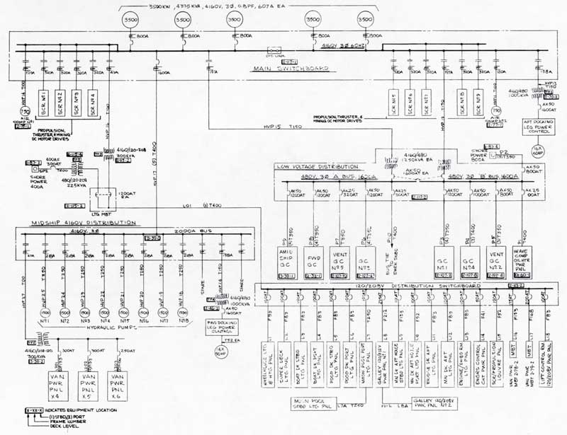
Figure 2-45. Basic Power Generation and Distribution
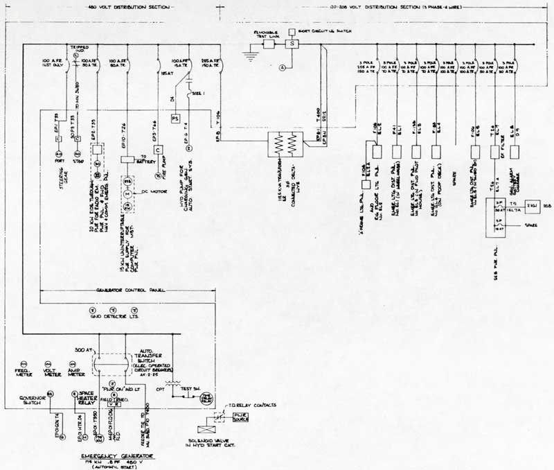
Figure 2-46. Emergency Power System
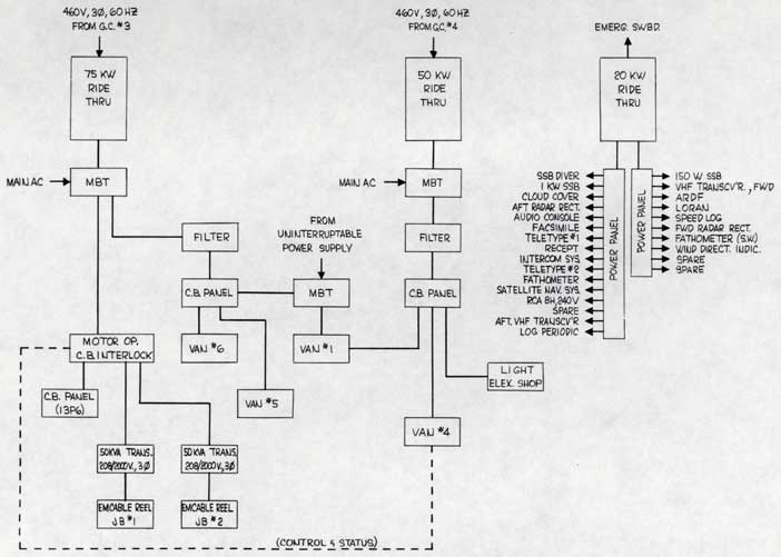
Figure 2-47. Ride-Through Power System
|
2-86 |
|
|
|
2-87 |
|
|
|
2-88 |
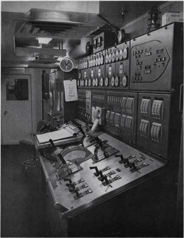
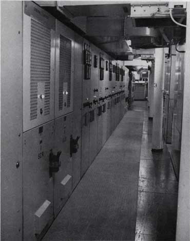
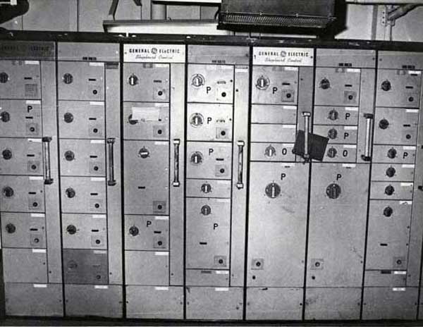
Figure 2-50. Typical Motor Control Center
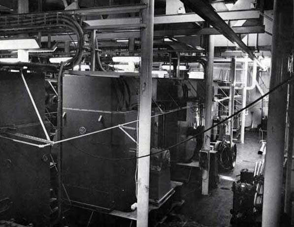
Figure 2-51. Main Generator Room
|
3-0 |
|
SECTION 3 - OPERATIONS |
|
3-1 |
|
The operation of an enormously complex system such as the GLOMAR EXPLORER necessarily requires highly sophisticated coordination of all activities. During the first years of operation, the extensive detailed procedures required have been developed. Crews and specialists have become highly trained in the use and behavior of this ship and its equipment.
Figure 3-1 gives an overview of the coordination used to control operating parameters of the ship, gimbal and pipe string. There is continual feedback between weather (sea state) and its effect on the dynamic pipe string and gimbal system. An example of the control of the step by step events involved in lowering subsea equipment to the sea floor is shown in Figure 3-2. |
|
3-2 |
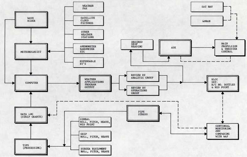
Figure 3-1. Operational Control