I find it difficult to talk about the history of the computer. The actual record is dreadfully short: almost nothing of consequence happened before the year 1935. We keep looking for a better story, but we inevitably end up grasping at straws.
Just look at what we’ve done so far. The “father of the computer” is no longer Konrad Zuse (Z1, 1938) or John Mauchly (ENIAC, 1943). Somehow, we pivoted to Charles Babbage — a 19th century polymath who never constructed such a device, and had no luck inspiring others to try. Not content with this injustice, we also turned “computing” into a meaningless word. On Wikipedia, the timeline of computer hardware includes mechanical clocks, dolls, weaving looms, and a miniature chariot from 910 BCE. It’s historical synthesis run amok.
To me, the calculator is a particularly regrettable casualty of this expansionist approach. Of course, the development of the calculator is intertwined with the history of the computer, but it deserves to be treated as a story of its own.
We know that sophisticated trade-based economies go back at least 5,000 years. Even in their early days, this required merchants to maintain accurate inventories, tally the proceeds, and keep track of debt.
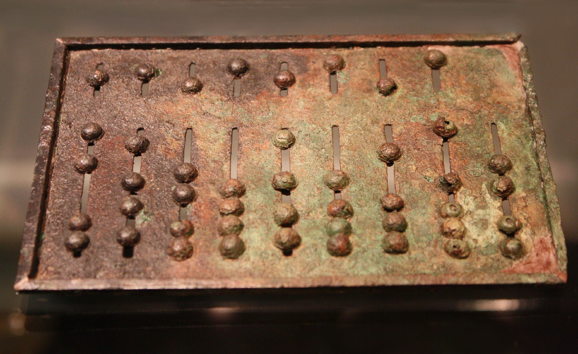
There is ample archeological evidence of specialized tools used to accomplish these tasks. For addition and subtraction, the implements included notched sticks and bones, rope tied with knots, and — later — rudimentary manually-operated “registers” such as the abacus:
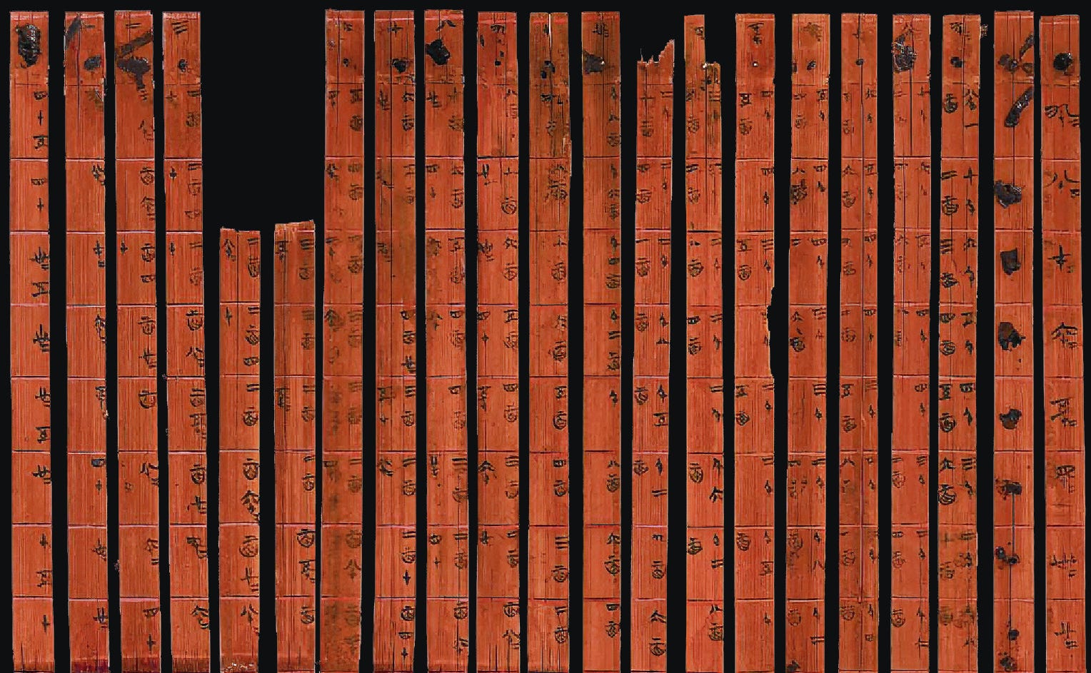
For multiplication, it was common to rely on lookup tables. The earliest known Babylonian multiplication table is 4,000 years old. The first decimal tables discovered in China date back to around 300 BC:
Both the abacus and the multiplication table remained in common use well into the 20th century — largely unchanged, but sometimes “updated” in wacky ways. For example, the following contraption from the early 1900s allows the multiplication two integers between 1 and 12. To obtain the result, the operator needed to align the legs of a monkey-shaped mechanical linkage:

Such novelties notwithstanding, the first “modern”, commercially successful mechanical calculation aid was the slide rule. The device, developed in the 1620s and usually credited to William Oughtred, exploits the fact that any two positive numbers can be expressed as exponents of a common base n. For example, if we choose base n = 2, we can write 16 as 24, while 42 is equal to approximately 25.3924.
It can be trivially shown that multiplication of numbers written in this form boils down to the addition of exponents:
\(n^a \cdot n^b = \underbrace{\underbrace{n \cdot n \cdot \ldots }_{a \text{ times}} \cdot \underbrace{n \cdot n \cdot \ldots}_{b \text{ times}}}_{a + b \text{ times}} = n^{a+b}\)
For example, we can calculate the result of 16 · 42 by adding the base-2 exponents for the two operands — 4 + 5.3924 = 9.3924 — and then calculating 29.3924 ≈ 672.
To implement this scheme in hardware, we just need two sticks with uniformly-spaced markings annotated with numbers that represent fixed increments of the exponent of a chosen base. Again, choosing n = 2 for illustration purposes, we could notch the sticks at one-inch intervals and then mark the subsequent notches as ¼, ½, 1, 2, 4, 8, 16, and so forth. Once we have this, we can multiply numbers by summing linear distances on the sticks, for example as shown below:
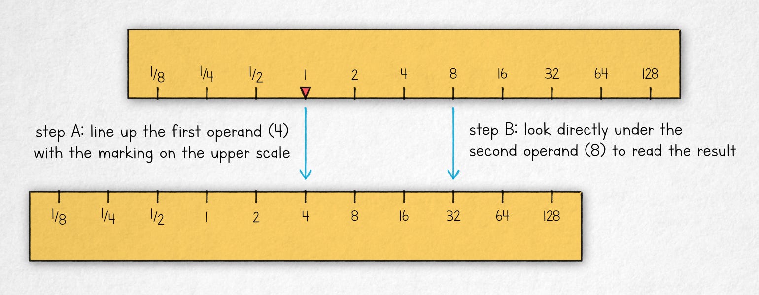
To calculate 4 · 8, we align the marked reference point (1) on the top scale with the first operand (4) on the lower scale. We then read the value directly underneath the second operand (8). The result is 32.
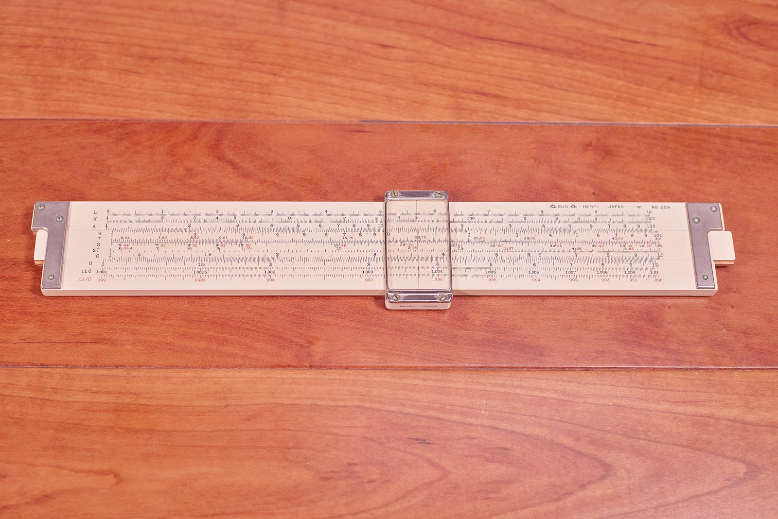
In practice, most slide rules had had two fixed elements (stators), a sliding portion in the middle, and a moveable cursor to facilitate precise readouts on a number of overlapping scales.
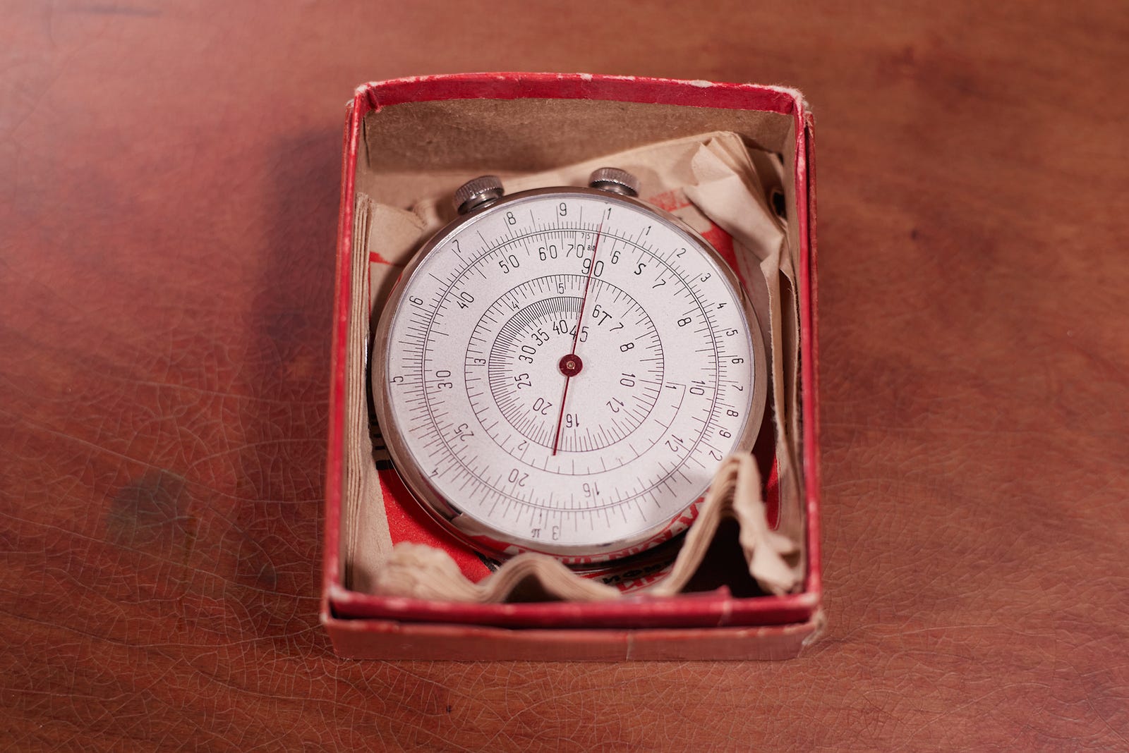
The slide reigned supreme well into the 1970s, an indispensable fashion accessory for every engineer worth a dime. It was manufactured in a variety of form factors, including some fairly unusual designs, such as this double-sided “pocket watch” made in the USSR:
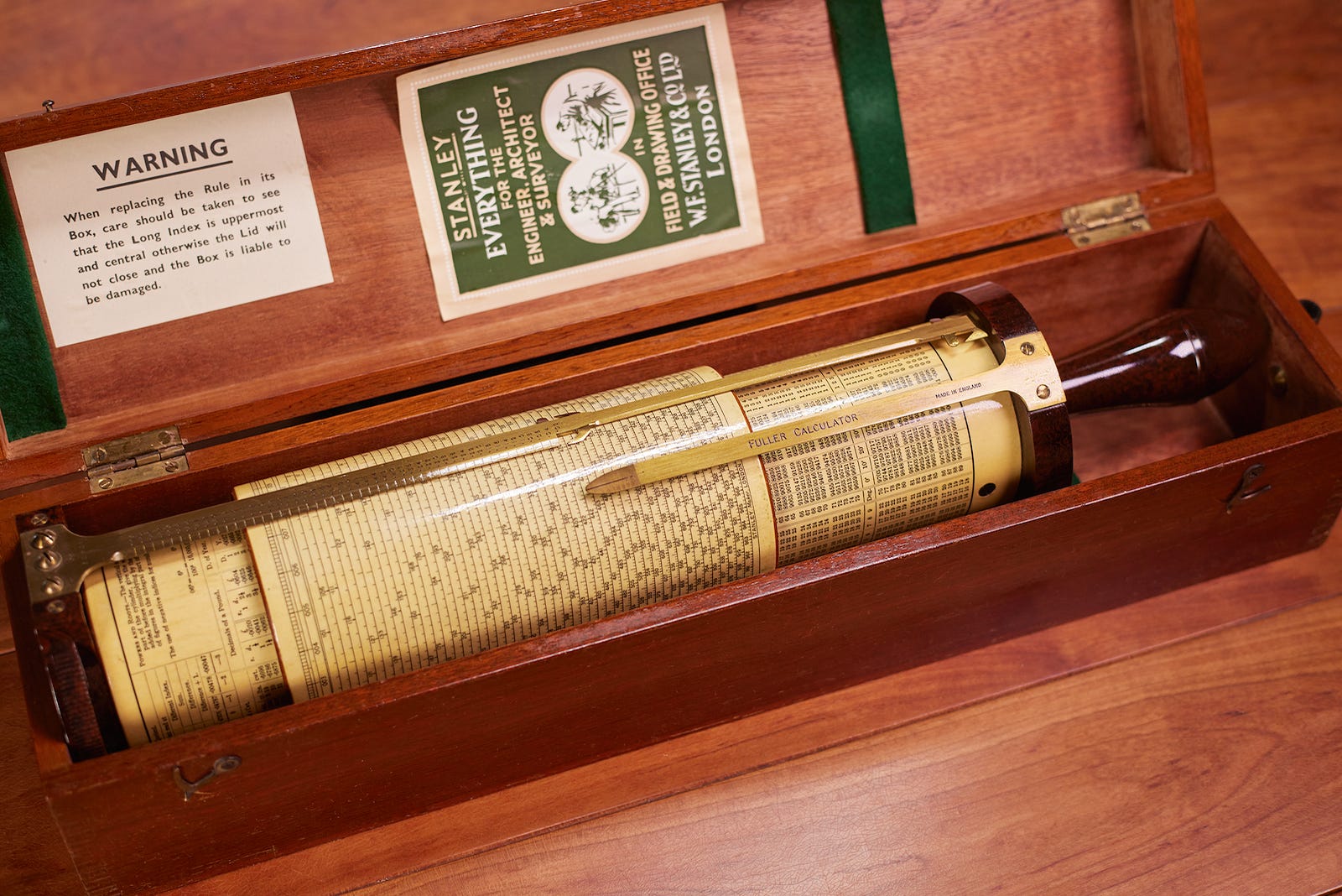
The slide rule depended on human eyesight to align the values and read out the result, so small devices weren’t particularly accurate. One ingenious workaround was to wrap a very long scale around a more compact Bakelite tube. “Tube-style” slides include the Otis King calculator and the Fuller calculator:
Although the slide rule has revolutionized engineering, it was more or less a one-trick pony. It could only tackle a specific subset of computations, required user training and care to avoid mistakes, and provided only approximate results. Because of this, it had limited utility to shopkeepers, accountants, and so forth.
The next major breakthrough in automation arrived with the invention of the carry mechanism. A counting device equipped with carry solved one of the most significant hurdles of using the abacus: the need to manually zero the column and add one to the next decimal position on overflow.
The first functional design of an adding machine with carry is conventionally credited to Blaise Pascal in 1642. The “Pascaline”, as it was called, was a rather bulky, stylus-operated device with a number of input disks:
About 50 units have been made during Pascal’s life; it wasn’t until the 19th century that simplified, portable adding machines started cropping up in everyday trade. The most rudimentary device of this type in my collection is an early Webb adder:
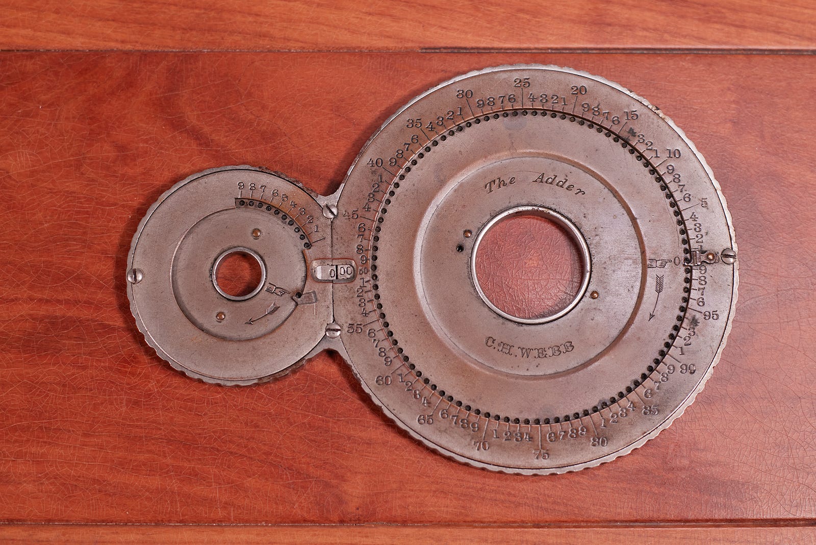
Similarly to the original Pascaline, the Webb adder is operated with a stylus. The large rotating disk on the right has a series of holes vis-a-vis numbers stamped on a fixed outer shroud. The numbers start at 3 o’clock and are incremented in the counterclockwise direction; the 3 o’clock position also features a protruding stylus stop. If you place the stylus in the position marked “5” and turn the disk clockwise toward the stop, you advance the number shown in the sight window (at 9:00) by five.
The operation can be repeated, with each stylus-entered value having a cumulative effect on the number shown in the sight window. This, in itself, is a simple addition mechanism. But crucially, on overflow — that is, right before the large disk completes a full turn and wraps back from “99” to “00” — an internal pawl advances the smaller disk on the left by one. The small disk has 50 positions (“0” to “49”), so the resulting range of the Webb adder is 0-4,999.
Many of the early attempts to improve the stylus-operated adder turned out to be dead ends; for example, the Adix calculator traded the clunky stylus for a keyboard, with ten keys that advanced the rightmost disk in a three-disk carry mechanism. Alas, this only allowed single-digit values — 0 to 9 — to be added in each step:
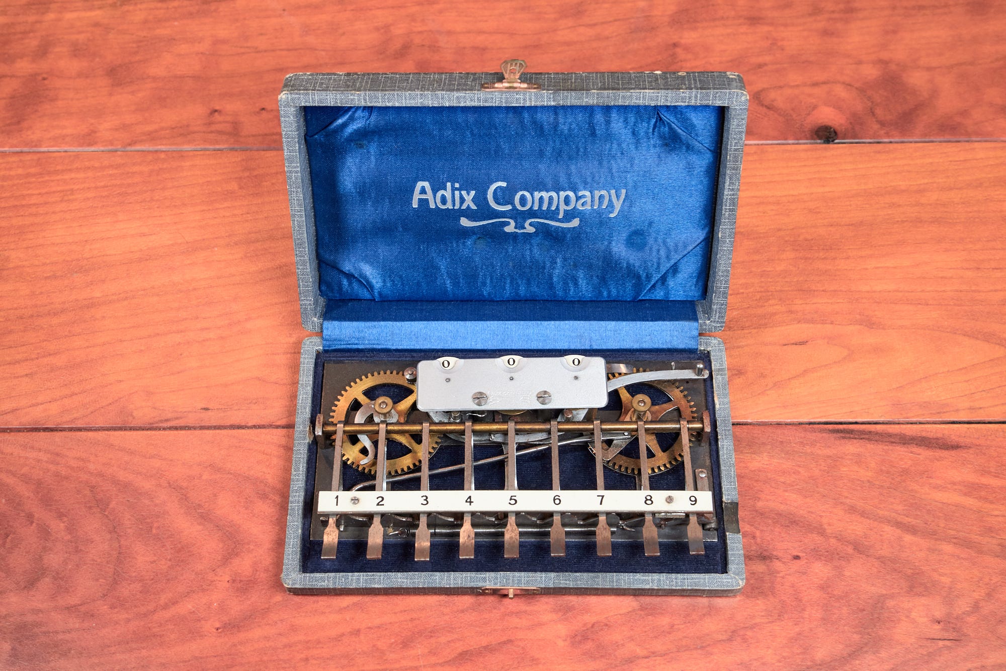
The mechanism of the Adix calculator is simple: there is a long, spring-loaded bar that runs under the keys. The bar has 𝘝-shaped cutouts for each key; pressing the key pushes on the slanted edge and moves the bar to the right. Each cutout has a different shape, so the distance traveled by the bar depends on the pressed key. This motion is then transferred to the gear mechanism.
A more practical design was to provide nine keys for each decimal position; a simple implementation of a nine-digit input mechanism is shown in the following Comptometer patent illustration from 1887:
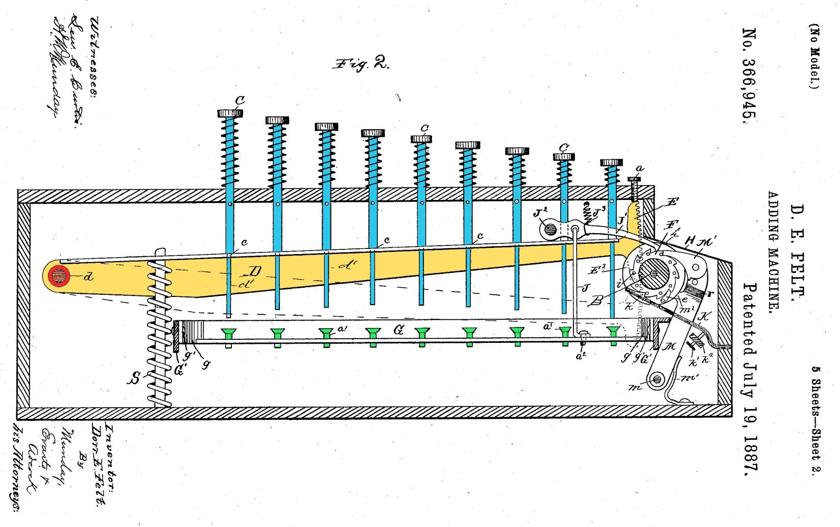
In this mechanism, a long arm (yellow) is attached to a pivot point on the left (red), and can be pushed down by pressing buttons (blue). The far end of the arm is equipped with a toothed rack; the rack turns the output gear — here, obscured by other parts of the mechanism — by an amount that depends on the pressed key. The key that’s closest to the pivot (“9”) point will move the rack more than the key on the other end (“1”).
Alas, this input method made the mechanism bulky and complex; for a ten-digit adder, you needed 90 keys:
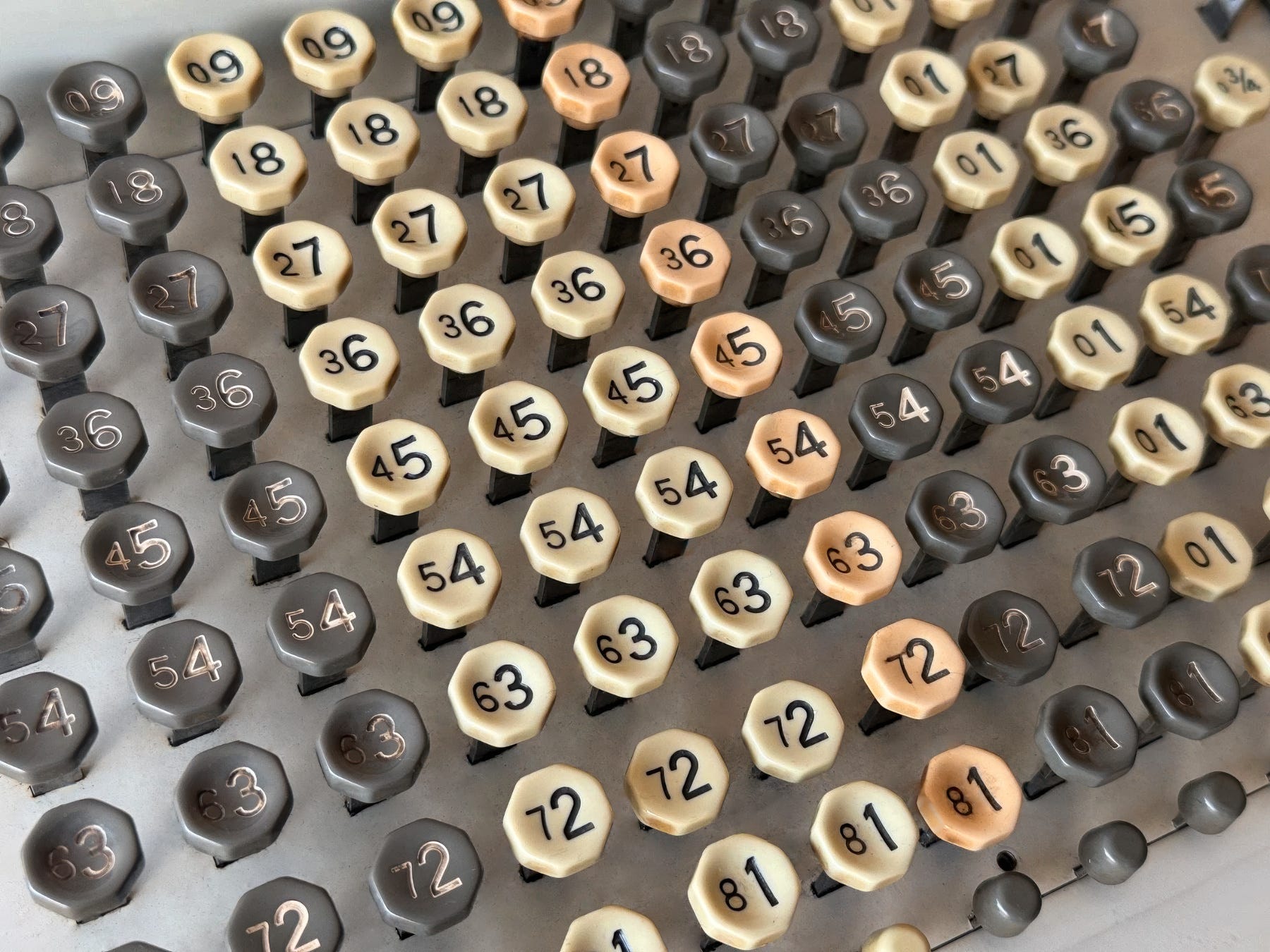
Because of this, full keyboards could be found chiefly on expensive, semi-stationary devices sold to big firms.
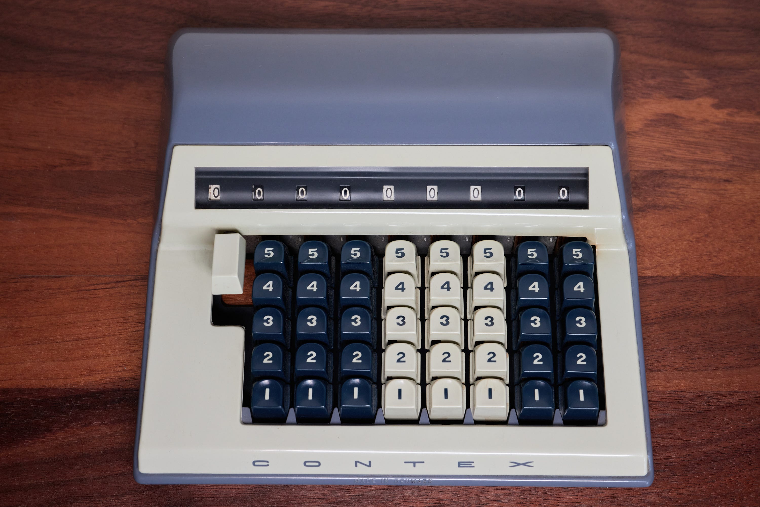
To build a more portable and affordable device for household and small business use, one could settle for a “half-keyboard” that only included digits from 1 to 5. In this design, any digits greater than five needed to be entered in two steps (e.g., 9 = 5 + 4):
Another approach was to stick to the disk-and-stylus input method, but use one sheet-metal disk per each decimal digit. Simple desktop adders of this sort resembled Pascal’s original design and continued to sell well into the 1970s:
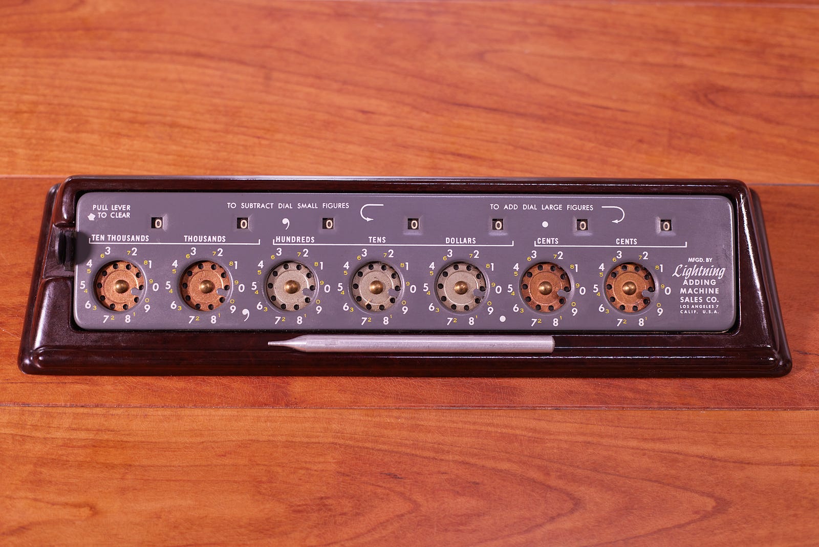
A number of other inexpensive 20th century designs relied on common-axis disks, chains, or sliding bars; in all cases, the fundamental principle was the same:
Adders, as the name implies, were good for primarily for adding. Subtraction called for mental gymnastics; using them for multiplication or division was theoretically possible, but required the user to repeatedly re-enter the same operand. This was neither convenient nor reliable.
The next major invention, credited to Gottfried Wilhelm Leibniz and dating back to 1672, is the separation of the input register and the output register (the “accumulator”). In Leibniz’s design, modifying the input register had no immediate effect on the final output value. The number would be added to (or subtracted from) the output only after the operator turned a crank. This was accomplished with a coupling mechanism known as the stepped drum:
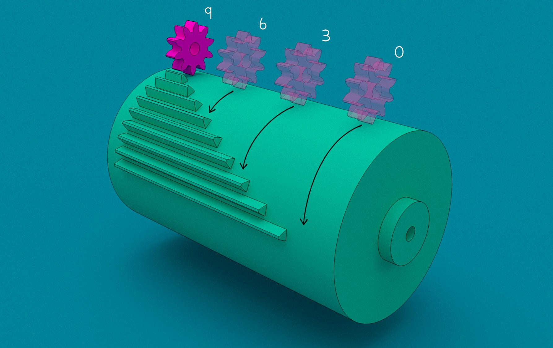
In a nutshell, the operator would manipulate an input slider or a knob that moved the small gear along the length of the drum. Depending on the selected input position, each rotation of the drum would then advance the gear by anywhere between zero and nine ticks.
Leibniz original design is shown in the following illustration:
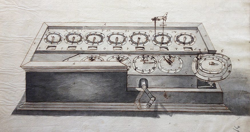
His “stepped reckoner” was never successfully commercialized; it appears that only two units might have been made. A modified version of the mechanism, the Arithmometer, entered mass-production much later, around 1851. This was followed by a wide range of pinwheel calculators that used an improved mechanism: a single, multi-digit drum with stacks of radially-oriented pins (blue) that could be retracted or extended depending on the position of the input lever mounted on an outer ring (orange):
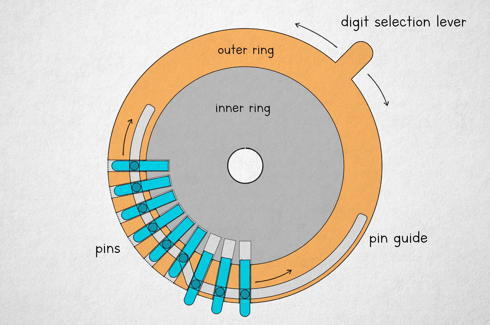
In the illustration above, the inner ring (gray) remains in position until the main crank is turned, so rotating the outer ring causes some number of pins to retract or extend. A more complete view of the internals of a typical pinwheel calculator is shown below:
In both of these designs — the pinwheel and the stepped drum — the entered value persists in the input register until manually cleared. Because of this, multiplication and division can be accomplished simply by spinning the crank a desired number of times. Further, a separate turn counter can be furnished to minimize the likelihood of errors; and a movable coupling between the registers may be added to permit rapid addition of the original number multiplied by a chosen power of ten.
A sophisticated mechanical calculator with all these features is shown below. The input register is visible on top, with the main crank to the right and a rapid clearing lever on the left. The output register is on the bottom right, next to the turn counter (bottom left). Two lever-like buttons in front move the output carriage left and right in relation to the input register:
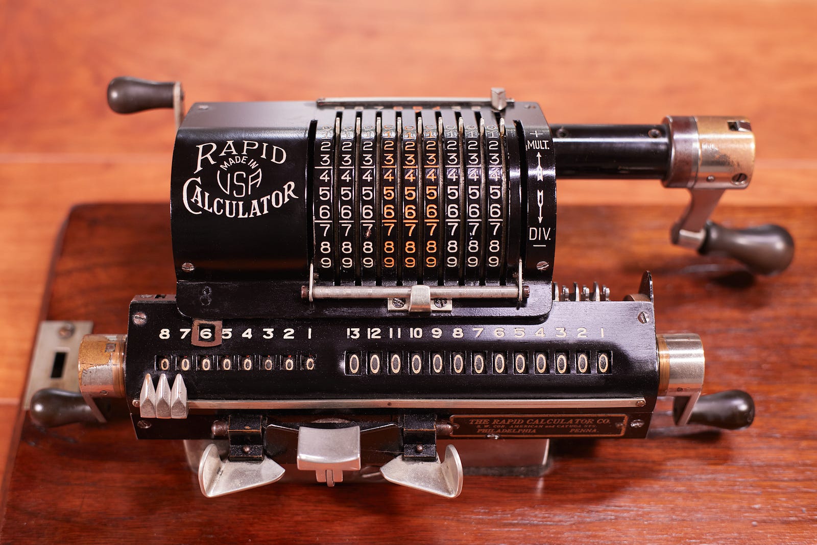
To calculate 79 · 123, one could enter “79” by manipulating small levers on top of the input register. The operator would turn the main crank three times to calculate 79 · 3 = 237. Next, they would shift the carriage, moving the input register by one decimal position to the left, and then turn the crank two times to add 790 · 2 = 1,580. Finally, the carriage would be shifted left again and the calculator would be cranked once to enter 7,900 · 1. In the following clip, I demonstrate the process using a similar machine:
If you’re unsure why this calculation technique works, note that adding 790 · 2 to the output register is functionally the same as adding 79 · 20. Similarly, the final 7,900 · 1 calculation can be restated as 79 · 100. In effect, we have calculated 79 · (100 + 20 + 3), or 79 · 123. The procedure is quite similar to the pen-and-paper long multiplication algorithm that’s sometimes taught in school.
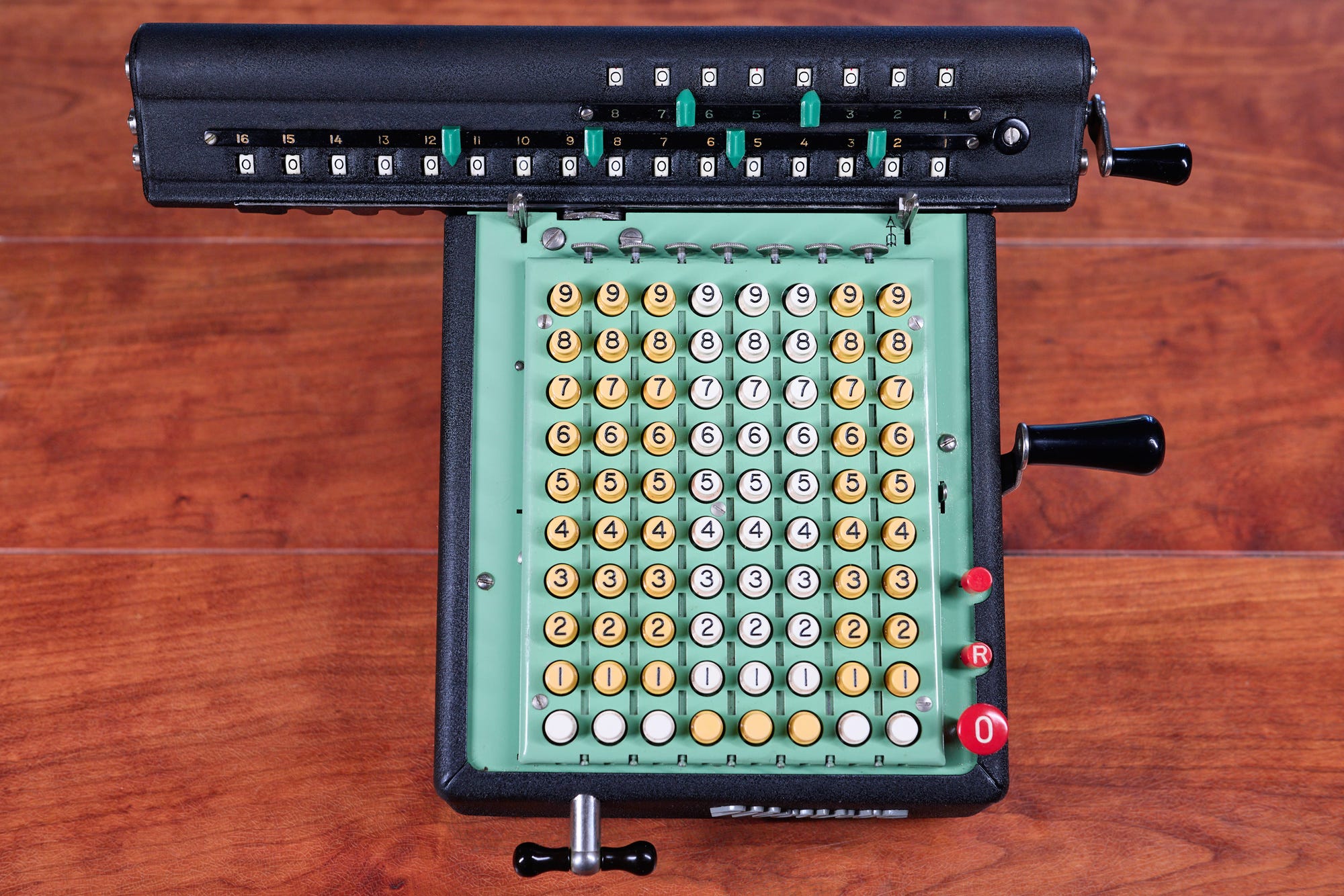
Lever- and slider-operated calculators were dominant in the early 1900s, but the same operating principle could be employed in a keyboard-based device. In these calculators, the last key pressed in each input column would latch until reset. In the following photo, the reset button can be seen in the bottom right:
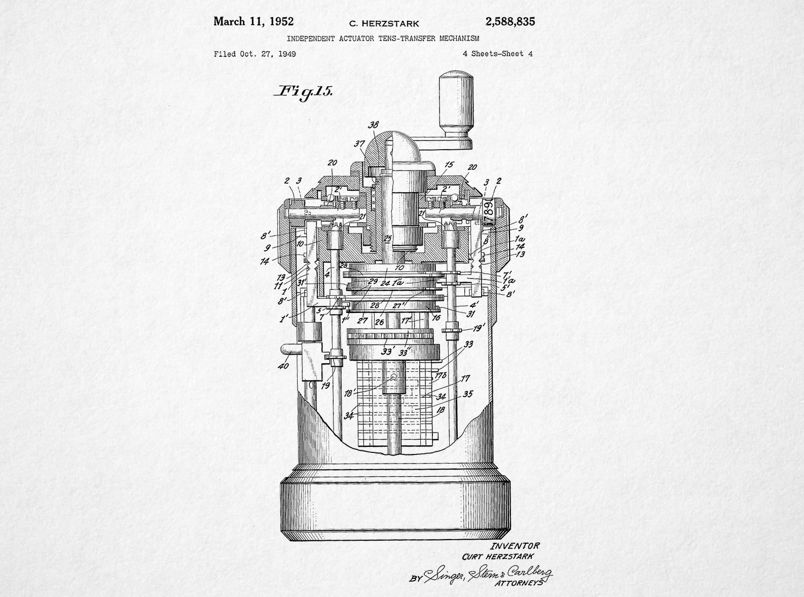
Although all desktop calculators of that era had their charm, the most sought-after variation of the theme is the palm-sized Curta: an unusual calculator envisioned by Curt Herzstark in the late 1930s. The design uses a single, vertical stepped drum surrounded by an array of output gears that can be moved up and down with sliders. A well-preserved specimen will usually fetch $1,500, compared to maybe $100-$300 for a desktop device:

Functionally, the Curta isn’t different from the desktop models discussed earlier, but its sheer level of miniaturization is the source of its lasting appeal. It is also fairly delicate; more than 100,000 have been made, but relatively few survive in a decent shape.
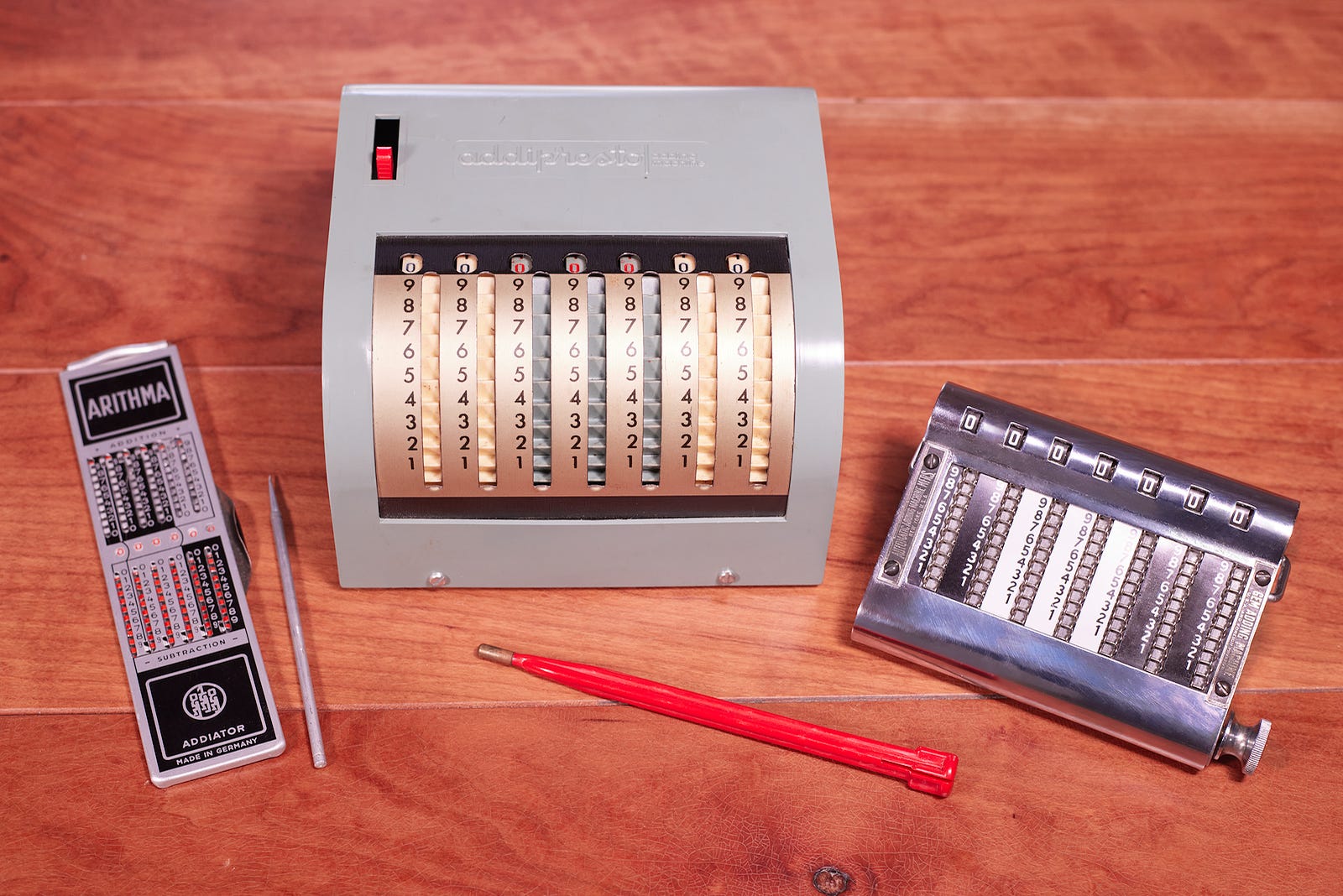
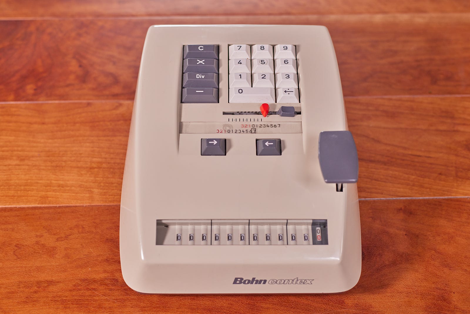
All kinds of fully-featured mechanical calculators continued to be made well into the second half of the 20th century. The designs were simplified, cranks were replaced with smaller buttons or levers, metal enclosures gave way for injection-molded plastics. Some manufacturers also experimented with automatically-advancing, spring-loaded couplings between the buttons and the input register. This allowed numbers to be entered sequentially on a compact ten-digit keypad, although the experience was rather awkward due to not having any immediate visual readout:
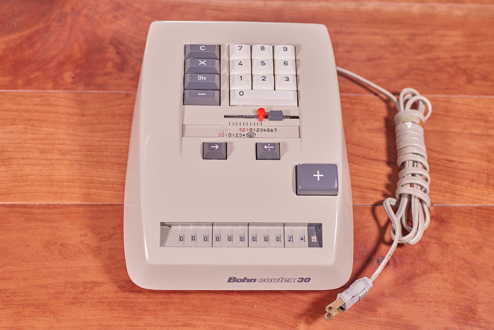
One would expect the electronic calculator to be the next step in the evolution of counting devices. Not so: it was simpler to fit mechanical calculators with a motor in the place of a lever or a crank. Here’s an example of another Belgium-made Bohn calculator that appears strikingly similar to the model shown moments earlier, except for an extra power cord:
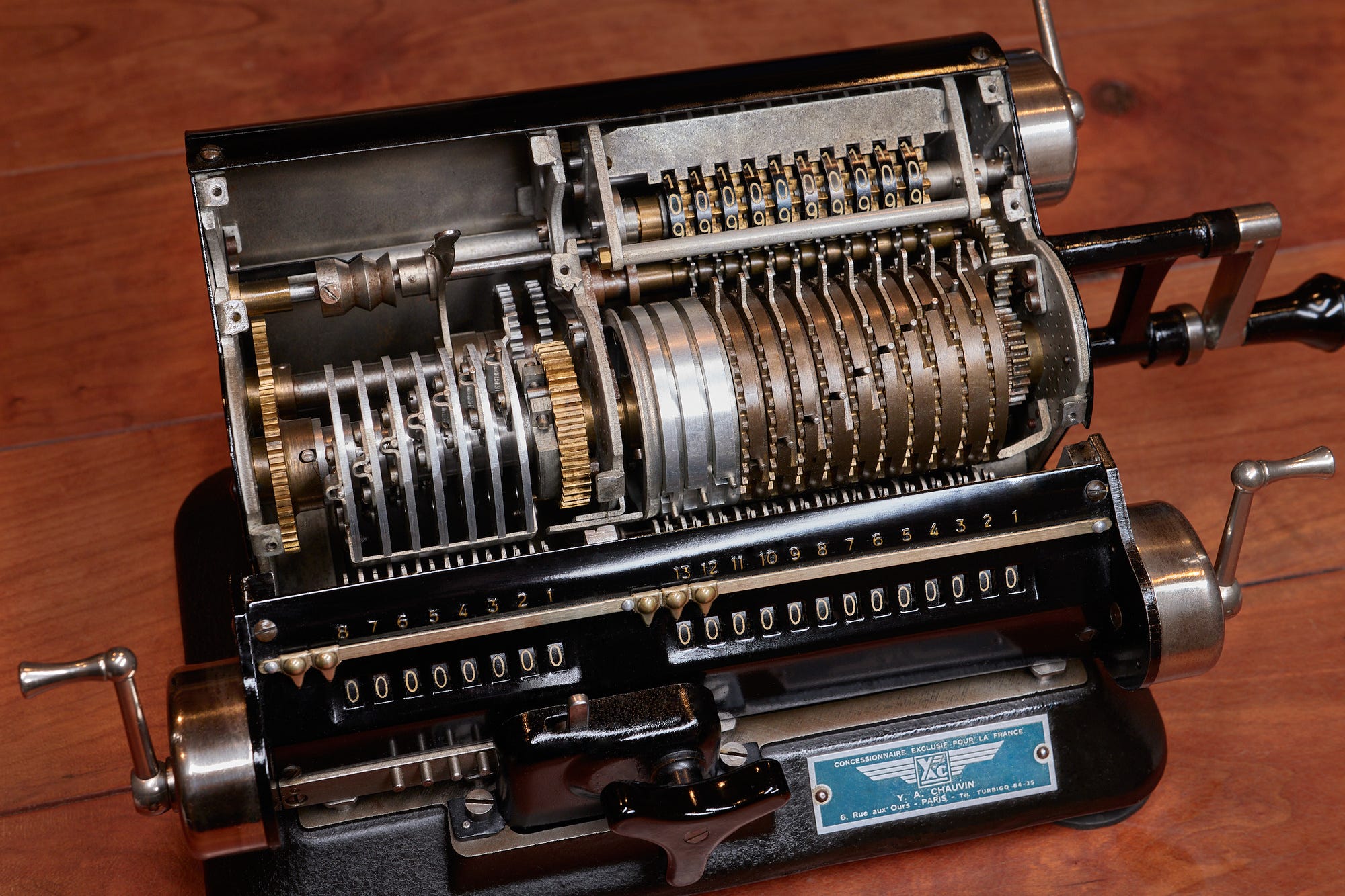
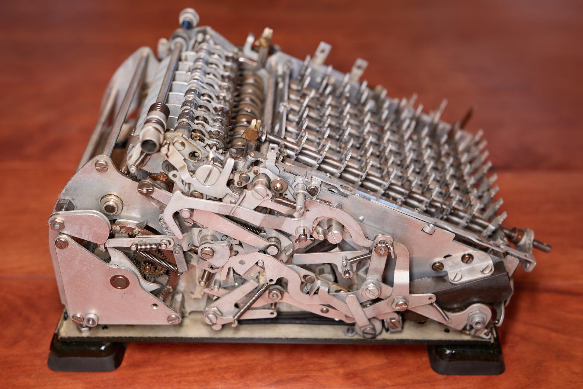
Although the device looks streamlined, the inner workings of these late-stage, four-function electromechanical calculators are remarkably complex. The photo below shows the innards of another calculator manufactured by Monroe. The motor is housed in the back:
Specialized electromechanical calculating machines, such as bombsights, started appearing around the time of WWII; the first pocket-sized transistor radios shipped in 1955. It might be surprising, then, that we needed to wait another fifteen years for electronic calculators to take hold. A major reason for the holdup was the lack of a display technology that would be compatible with everyday home or office use.
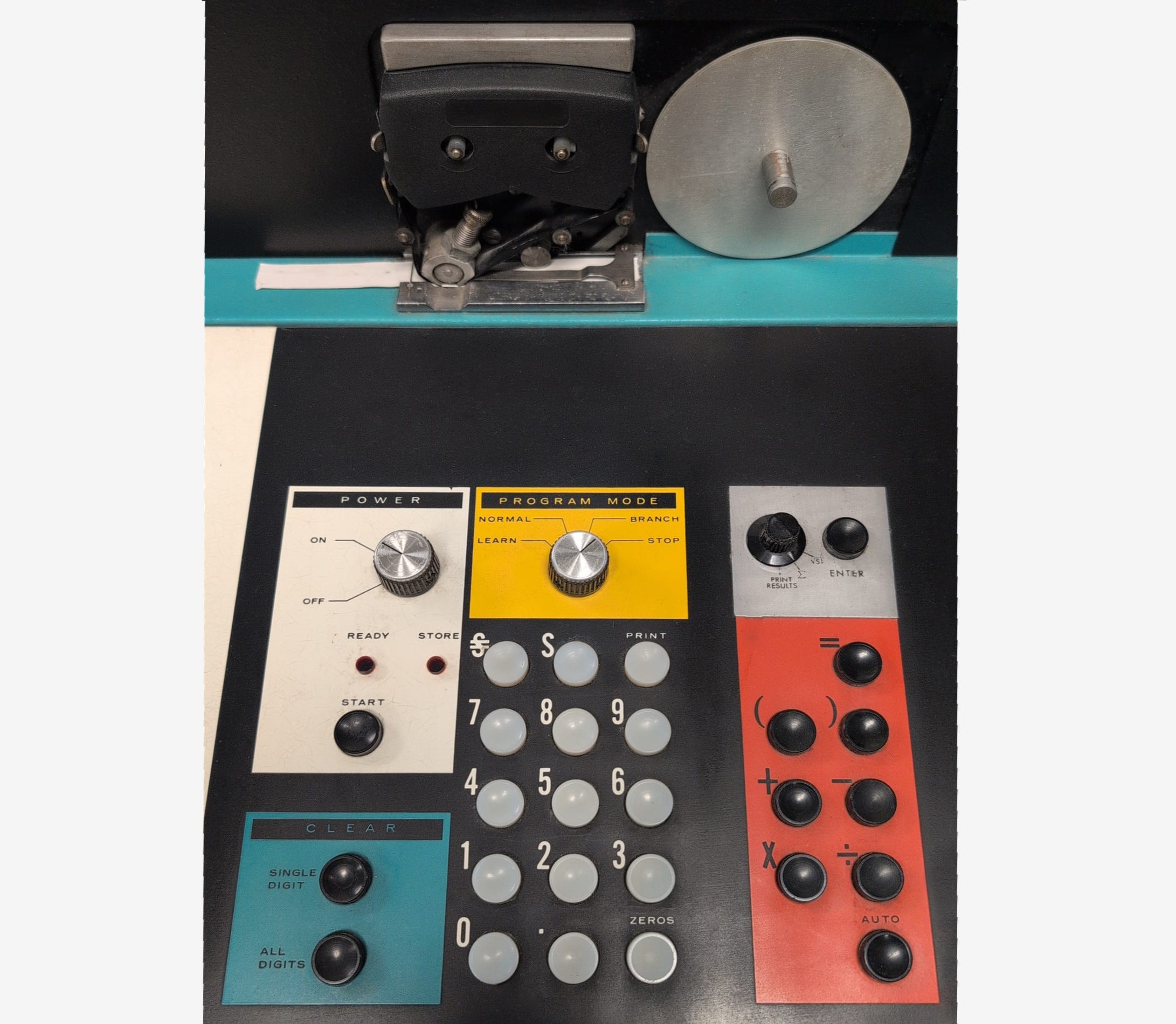
A handful of early digital calculators were equipped only with a printer; a delightful example was the Mathatronics Mathatron, circa 1963:
Some other designs relied on hundreds of incandescent lamps to highlight the currently-active digit for each decimal position, as seen in the desk-sized, 300-pound, relay-based Casio 14-A (1957).
More practically, several manufacturers experimented with cathode ray tube (CRT) displays:
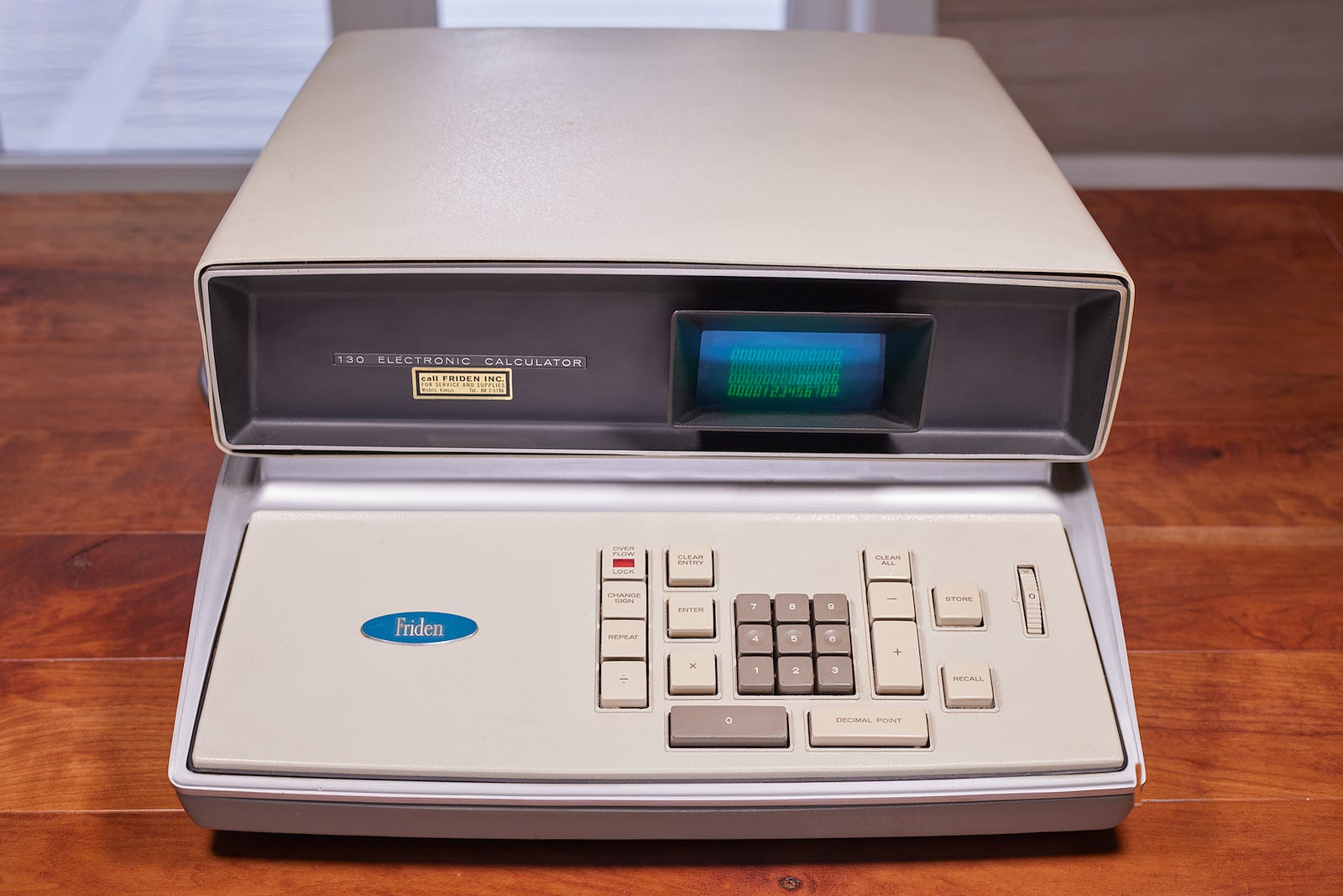
This particular specimen from my collection is the first transistor-based calculator to be mass-manufactured. It dates back to 1964, features reverse Polish notation, weighs over 40 lbs, and came with an original MSRP comparable to that of a nice car. The design uses acoustic (magnetostrictive) delay line memory and contains no integrated circuits whatsoever; all the CRT digit drawing was done with discrete components.
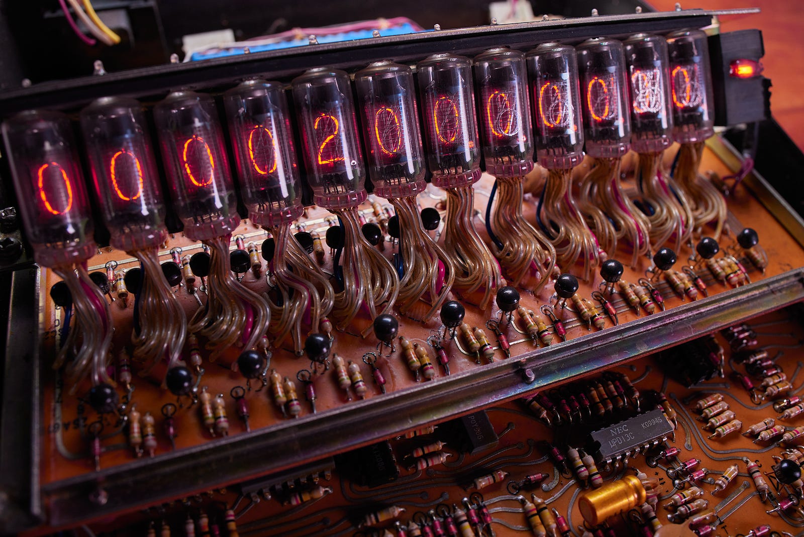
A more practical solution to the problem was the nixie tube: a gas-filled vial containing a stack of intricately-shaped wires. With around 180 V applied to the terminals, the gas emitted a pleasant orange glow in the immediate vicinity of the currently-energized wire:
Nixie tubes can be found in what can be described as the first “electronic” calculator: Sumlock Anita Mk VII / VIII, sold in Europe starting in the late 1961. The Anita traded electromechanical switching of Casio 14-A for nearly two hundred gas-discharge tubes, about a dozen vacuum tubes, and several hundred solid-state (diode-like) selenium rectifiers. Interestingly, it retained the clunky, nine-keys-per-decimal-position input scheme seen in the Comptometer and in some other purely-mechanical designs.
Following in Anita’s footsteps, the first commercially successful calculators of the era were mains-powered and used a mix of discrete transistors and low-complexity, general-purpose integrated circuits. It follows that they still took up quite a bit of desk space, although nowhere near as much as the CRT monstrosity mentioned earlier in the article.
A distinctive feature of these early designs was their rather leisurely computation speed. This was especially evident for more complex operations, such as multiplication and division; as well as premium “scientific” features such as square roots, logarithms, and trigonometry. In the following video, I demonstrate the processing speed of Compucorp 110 (1971):
For cost- and size-saving reasons, the devices lacked many of the convenience features we now take for granted. For example, quite a few calculators had no power-on-reset circuitry, so the equipment booted to an unpredictable state and had to be manually zeroed before use. In the same vein, many units had no floating point capabilities (although it was common to see a fixed decimal point that could be moved with a knob). Finally, a good number of devices lacked true support for negative numbers, requiring the operator to keep track of signs.
Because of their cost and relative bulk, nixie tube calculators would be an unusual sight in a private home, but the technology enjoyed substantial adoption in the world of business and science.
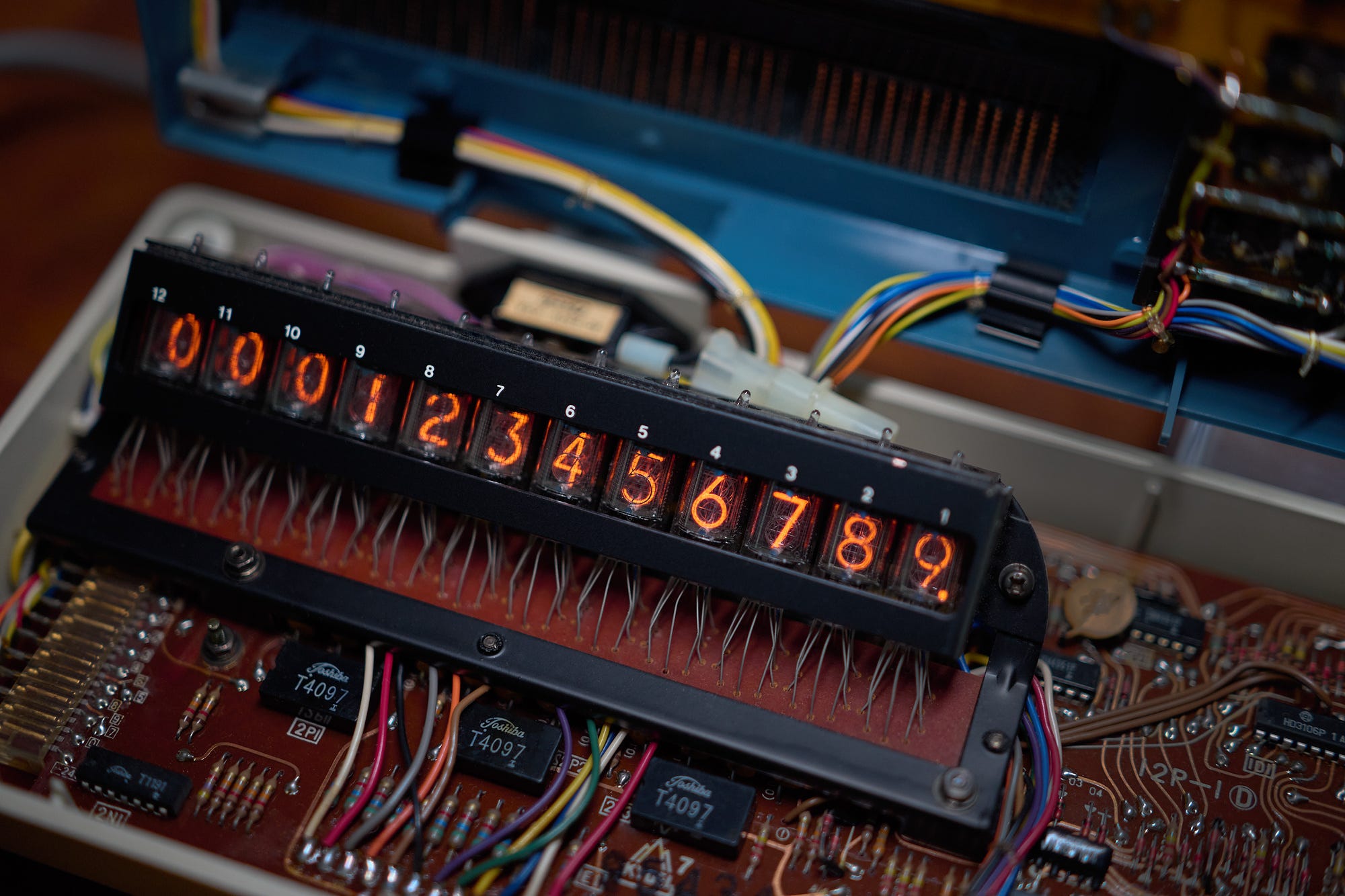
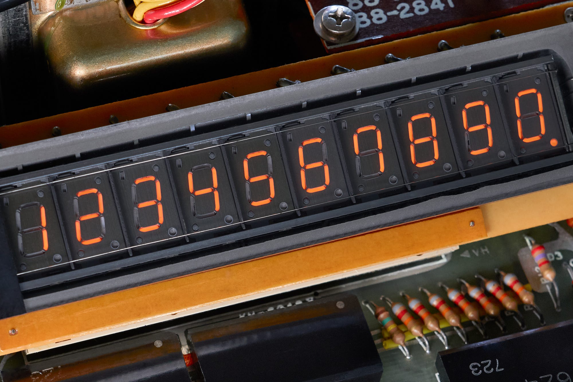
As hinted earlier, calculator displays continued to be a significant limiting factor for calculating machines; bulky, high-voltage tubes were difficult to integrate into battery-operated devices. The situation improved a bit with the advent of streamlined “Panaplex” displays. These displays relied on the same operating principle and still required high supply voltages, but came in the form of more rugged, self-contained 7-segment display modules:
Nevertheless, to fully realize the dream of the handheld calculator, the industry needed a different approach. The answer turned out to be the vacuum fluorescent display, or VFD.
The new technology, pioneered by Sharp, relied on a heated cathode in a vacuum. With a sufficient voltage applied, electrons are emitted by the cathode and strike a phosphorescent material to produce visible, blue-green glow. Because the emission of electrons is aided by thermal energy, the design requires a much lower operating voltage — around 15 V — and offers better contrast than neon tubes.
The following photo shows one of the earliest portable calculators, Sharp EL-8. The device tipped the scales at 1.5 lbs and was too big to fit in a typical pocket. Still, it heralded a new era of calculating on the go:
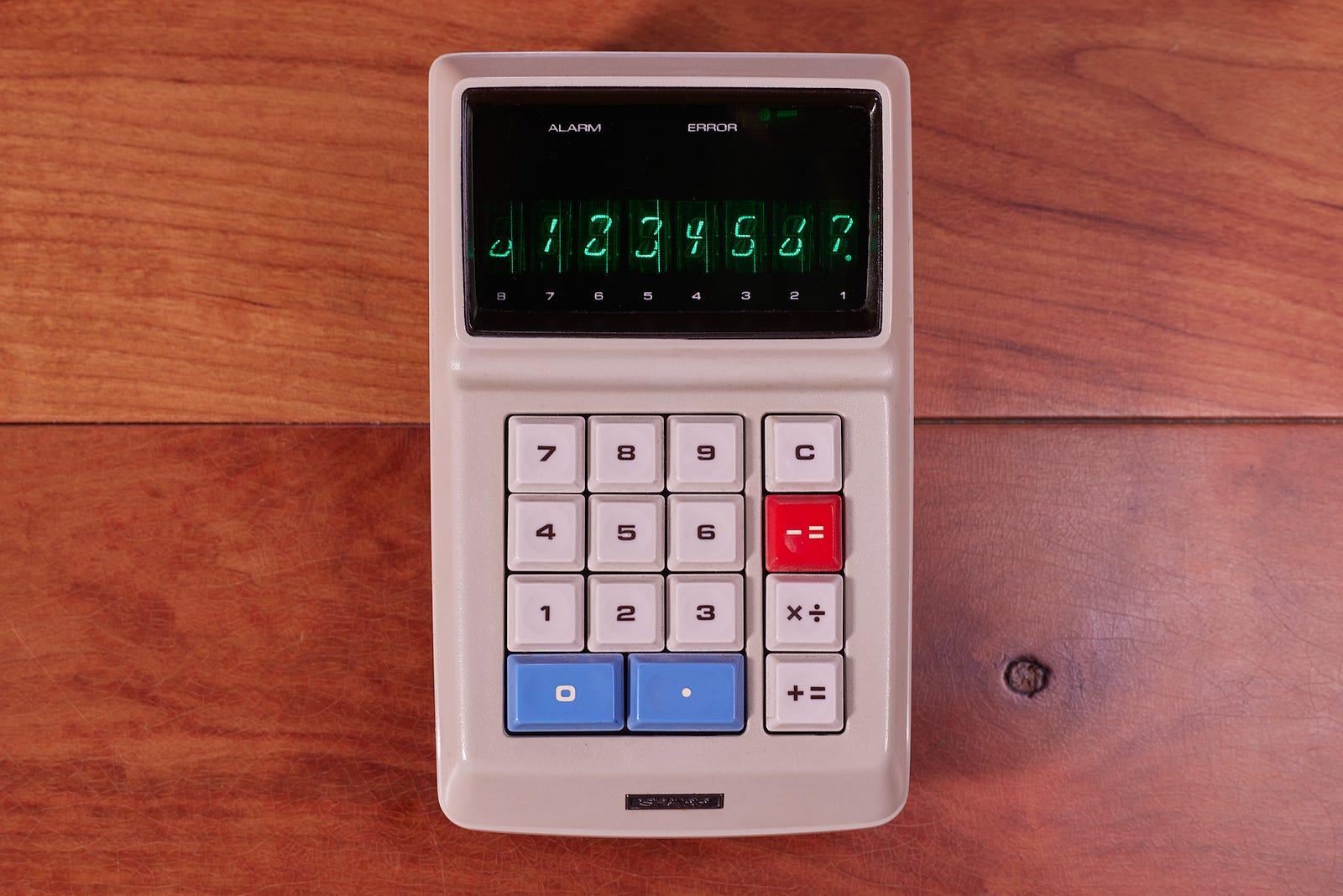
Note the unusual 8-segment digit pattern of eight individual “Itron” display tubes. The calculator also used a fairly peculiar multi-function key layout. This was likely a cost-saving measure, as the keypad relied on costly (but superbly reliable) magnetic reed switches. Internally, the circuitry was still rather bespoke: the device used four general-purpose logic chips, a timing IC in a metal can, and nine driver chips for the display itself.
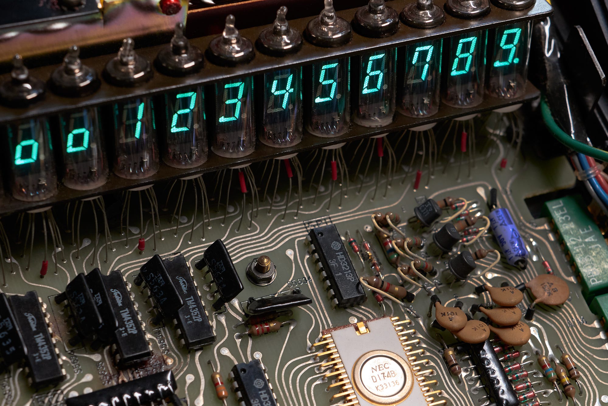
Novelties such as the wacky Itron display tube soon went the way of the dodo, the industry converging on the familiar 7-segment approach. These segmented displays combined low cost, high reliability, and excellent legibility:
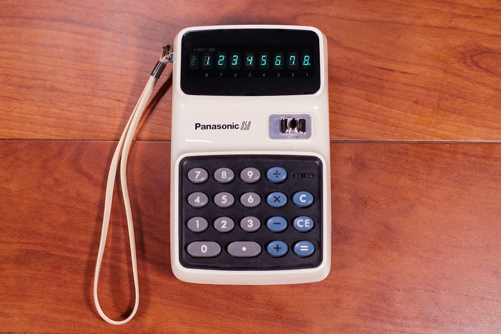
Note the neatly stylized “4” on the display of this Panasonic calculator. The internals of this generation of devices are streamlined too; this particular unit features a Texas Instruments TMS0100 series chip that combines ROM, RAM, timing, and arithmetic logic on a single silicon die.
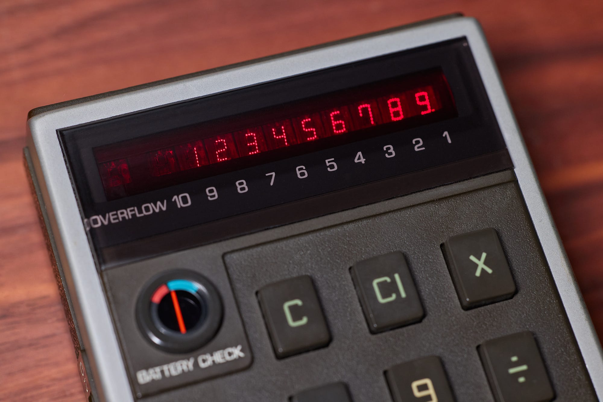
Vacuum fluorescent displays were a massive leap forward, but the technology still had marked disadvantages. For one, as noted earlier, it needed a heated cathode and a modestly elevated voltage to trigger the emission of a sufficient number of electrons. All of this wasted electricity and required specialized driver ICs.
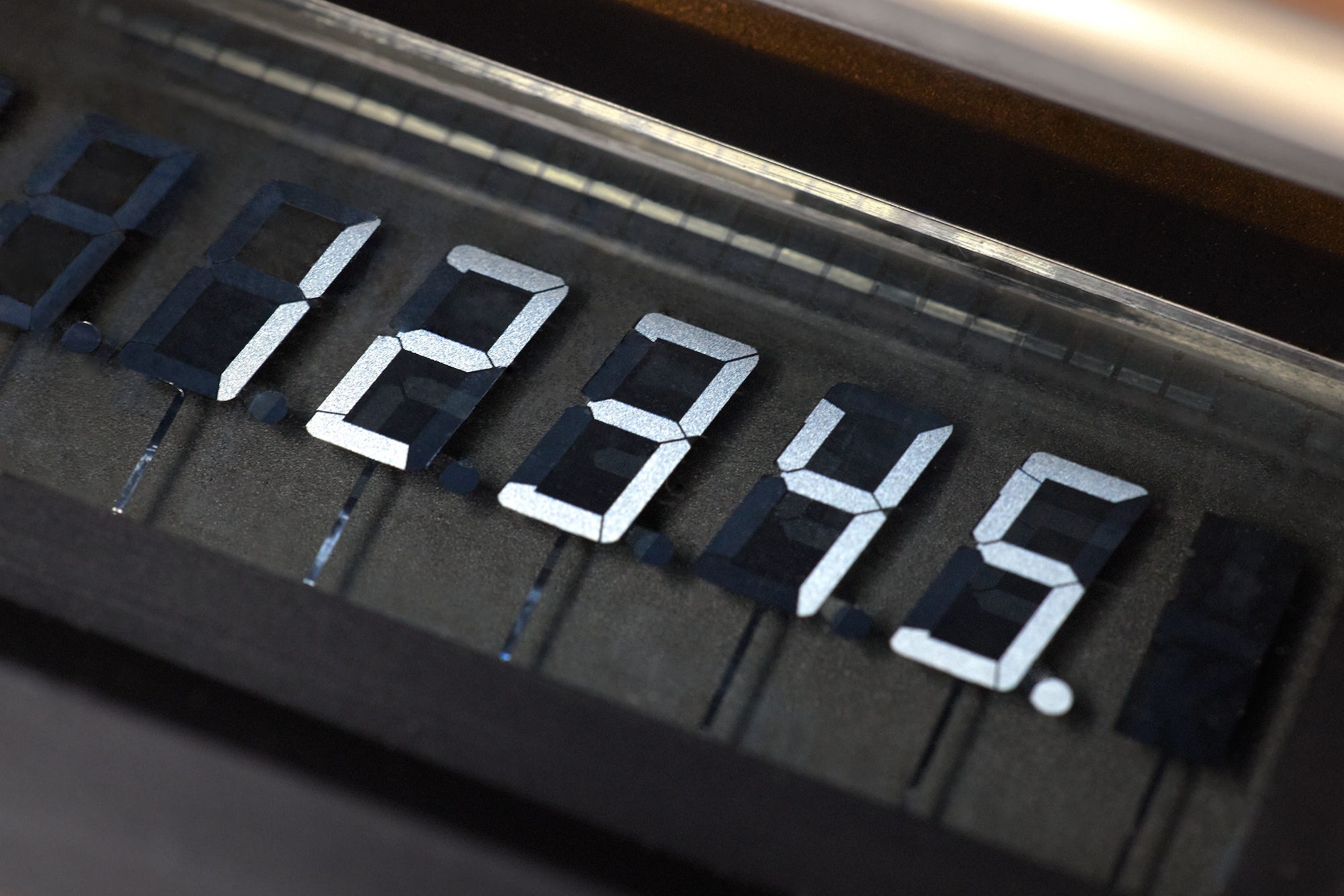
Because of these shortcomings, VFDs were eventually ditched in favor of another nascent display technology: the light-emitting diode. LED displays, initially available only in red, weren’t nearly as pretty as VFDs, but they made up for it in improved power efficiency and the ability to run off as little as 1.9 V:
The first commercially successful LED calculator was the rather ugly Busicom LE-120; the Busicom product also earns the distinction of being the first to use a dedicated “all-in-one” calculator chip: Mostek MK6010.
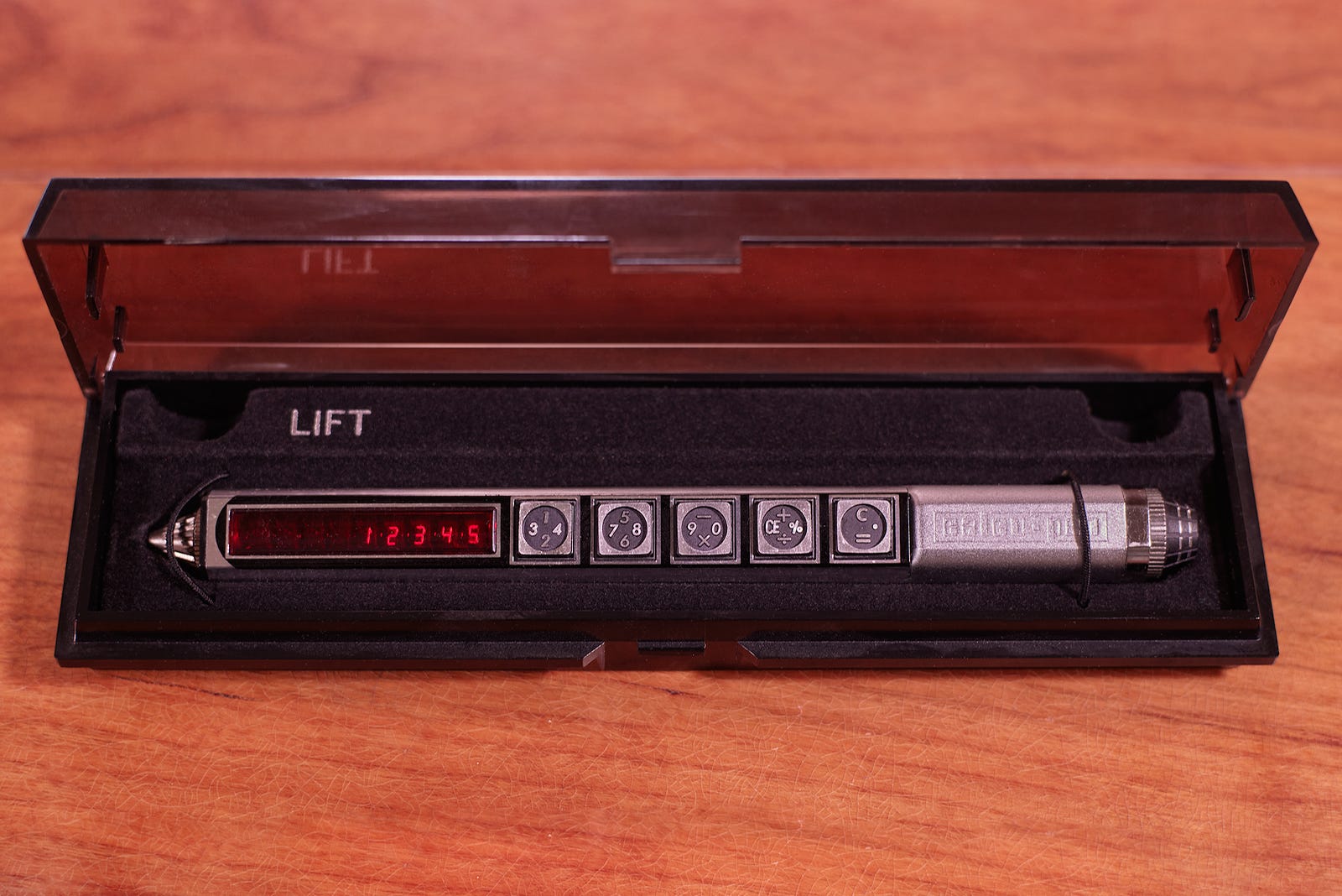
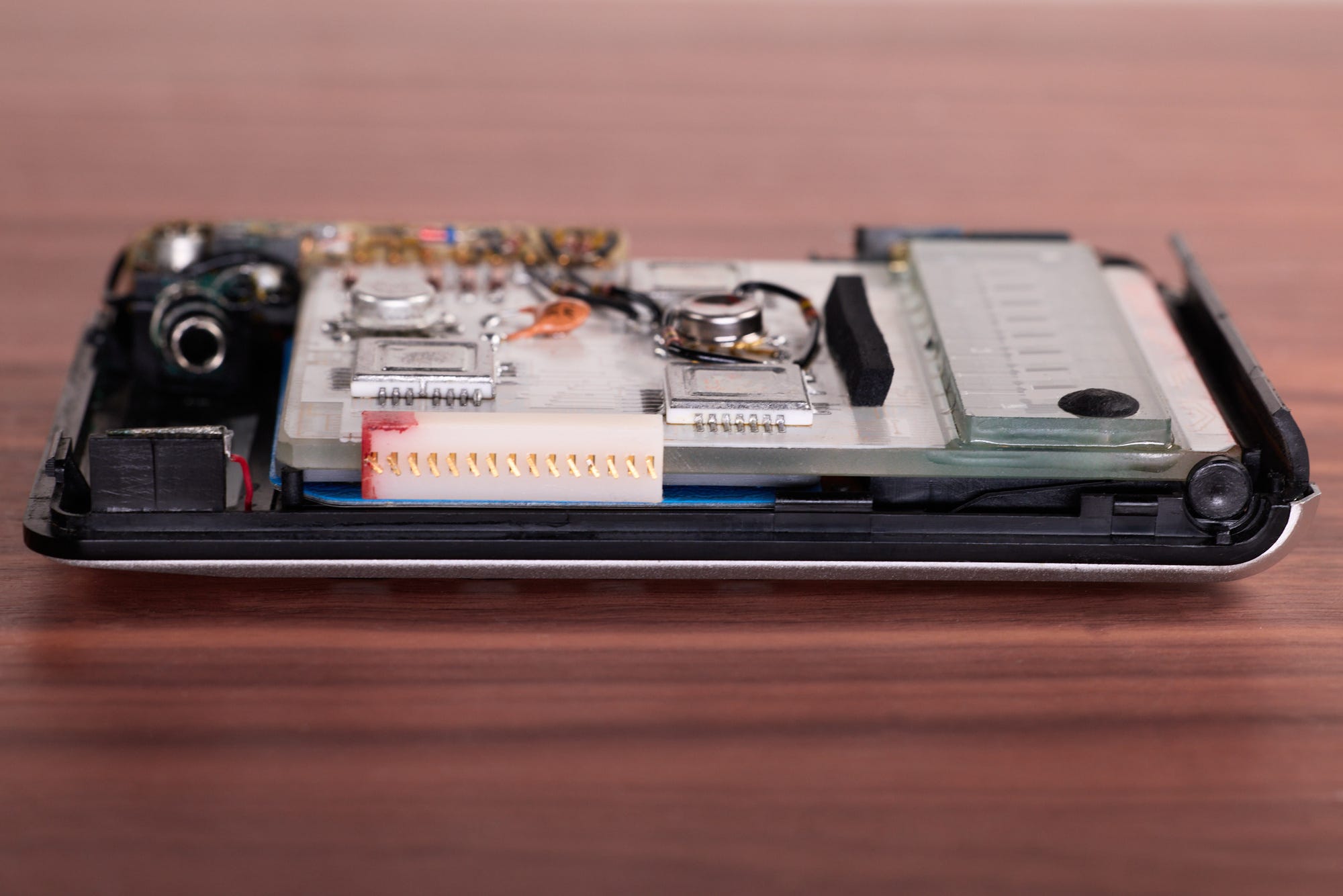
My favorite design of this era is probably the wildly impractical Calcu-Pen, running off a single “N” type cell:
The final chapter in the evolution of calculator form factors is the development of liquid crystal displays (LCDs). LCDs don’t emit their own light; instead, they exploit the fact that the optical properties of certain organic substances change when subjected to an external electric field. Sharp was arguably the first to commercialize the tech in 1973:
The aesthetics of reflective LCDs are a step back compared to what came before, but the technology draws virtually no current in their steady state. Because of this, a new breed of calculators could run for hundreds of hours off a single AA battery:
You could even power a calculator with a solar cell or a watch battery. Heck, with the advances in chip design, you could put a calculator in a wristwatch if you wanted to!
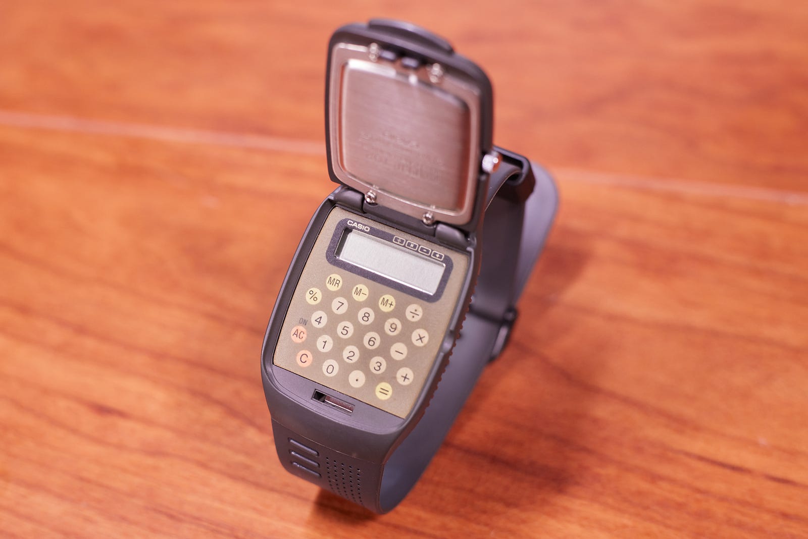
Readers old enough to remember the 1990s probably recall the nerdy fashion accessory that was the calculator watch. Here’s a particularly wacky design from Casio — a flip-top watch face that revealed a numerical keypad and an LCD:
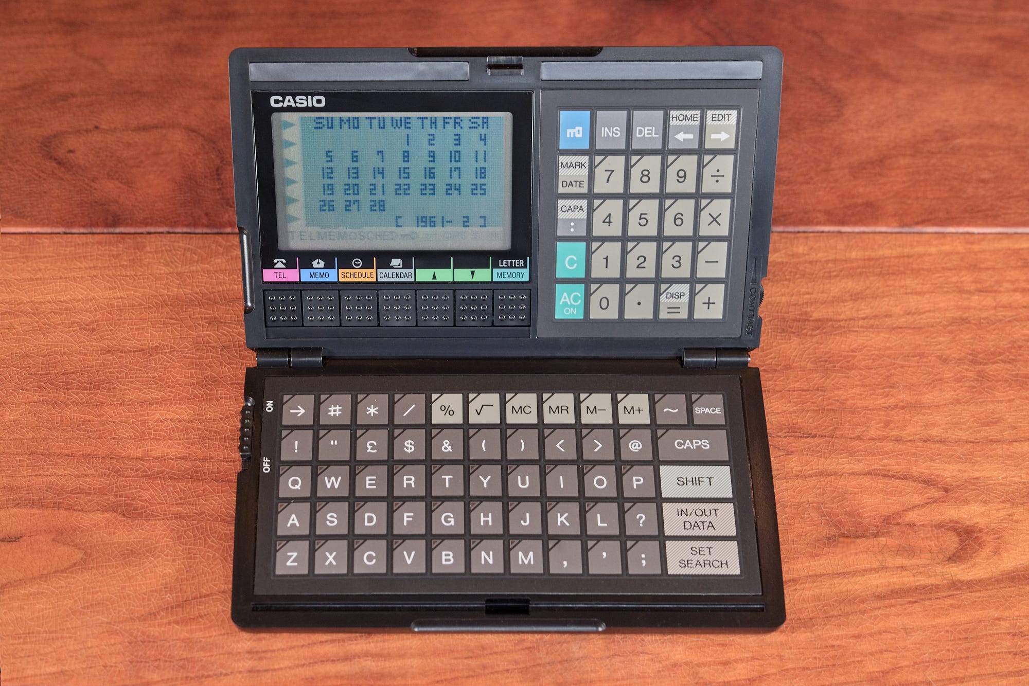
For a while, it seemed that counting devices were destined to become the hubs of our digital lives. In the 1980s and in the early 1990s, there was an explosion of "personal assistant” devices developed by calculator makers, keeping the traditional calculator functionality in the forefront. The units included features such as phone books, calendars, and “to do” lists. Casio was once again ahead of the pack:
Of course, that future wasn’t meant to be. The calcu-assistant ended up getting upstaged by the cell phone. Today, you can still buy a calculator — but why would you ever carry one?
👉 For a followup article on the history of RAM, click here. A catalog of other articles on this site can be found on this page.
I write well-researched, original articles about geek culture, electronic circuit design, algorithms, and more. This day and age, it’s increasingly difficult to reach willing readers via social media and search. If you like the content, please subscribe!