floppy3.5 is a 3.5" floppy disk portable WiFi NAS. It reads photos from the floppy disks of old digital cameras like the Sony Mavica. It shows the photos on a web page through WiFi. It can also copy the photos to a microSD card expanding the amount of photos you can take on the move.
It can read any FAT12 1.44 MB HD disk. It shows the files in the root folder of the disk on the web page and can copy them to the SD card

 slimline 3.5" drive ──26-pin──▶ RP2354A ──SPI──▶ ESP32-S3 ──WiFi──▶ browser (floppy.local)
                                 controller        bridge   └──▶ microSD (/DISKnnnn/)
The two processors are on one custom PCB. The RP2354A controller uses the
Greaseweazle host protocol. You
can also use the gw tool with the controller through the secondary USB. The ESP32-S3
bridge controls the controller through a custom SPI link. The bridge decodes
the disk and shows the photos on a web page. Both are OTA updatable
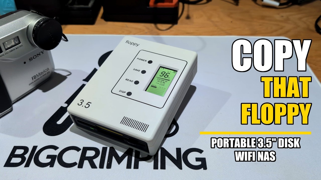
▶ Click the picture to see floppy3.5 in action on YouTube
History
The first prototype used an ESP32 development kit, a Greaseweazle-type adapter board with the Greaseweazle firmware, and a desktop floppy drive:

The current design has the two processors, the charger and the power supplies on one PCB and targeting a slimline drive:

Contents of the repository
| Path | Contents |
|---|---|
hardware/gw-esp32-2_gerber.zip |
Gerber files to make the PCB (copper, solder mask, paste, legend, outline, PTH and NPTH drill) |
hardware/schematic.pdf |
The schematic, with the part values |
hardware/assembly.pdf |
The assembly drawing. It shows the position of each part |
mech/ |
STL and 3MF files to print the housing |
assets/ |
The pictures in this file |
firmware/rp2354/ |
The controller firmware (pico-sdk) |
firmware/esp32/ |
The bridge firmware (ESP-IDF) |
firmware/esp32-bringup/ |
A self-test for a new board |
firmware/common/ |
The SPI link frame layout. The two firmwares use this file |
Firmware files that are ready to install are on the GitHub Releases page.
Parts
Parts on the PCB: Refer to the schematic (hardware/schematic.pdf). The
main parts are:
- An ESP32-S3-WROOM-1-N16R8 module (16 MB flash, 8 MB PSRAM)
- An RP2354A controller
- SN74LS07 bus buffers
- A BQ25180 charger and a MAX17048 fuel gauge
- An LTC2954 power button controller
- A TPS63020 regulator (3.3 V) and a TPS61022 regulator (5 V for the drive)
- An RV-3028-C7 real-time clock
- A microSD socket
Other system parts:
| Part | Notes |
|---|---|
| Slimline 3.5" floppy drive, 26-pin | The design uses a Sony MPF920-type slimline drive. The drive uses only 5 V |
| 1S LiPo battery, size 606090 (approximately 4000 mAh), 3 wires with NTC | Connect it to J9 (JST GH, 3-pin) |
| 1.9" ST7789 IPS LCD, 170×320, 8-pin SPI module | Connect it to J2. Refer to LCD connections |
| microSD card | Use the FAT32 format |
| 4 M2.5×16 cap screws and 4 M2.5 heat-set inserts | These attach the two halves of the housing (hole 3.4 mm, depth 4 mm) |
| 4 M2 heat-set inserts and M2 screws | These attach the LCD module to the lid |
| Thin insulation tape (0.5 mm maximum) | Put it between the top of the drive and the PCB |
Build the board
WARNING: Make sure that the polarity of the battery connector is correct before you connect the battery. Incorrect polarity can cause damage to the LiPo battery. A damaged LiPo battery can cause a fire.
- Order the PCB. Use the files in
hardware/gw-esp32-2_gerber.zip. - Order the parts and assemble the board. Use the schematic and the assembly drawing.
- Install the LiPo battery. The board does not start without the battery. With only USB power, the voltage decreases too much at power-on.
- Install the
firmware/esp32-bringup/firmware. - Make sure that all tests pass. The results show on the USB serial console.
- Install the usual firmware.
The PCB was kindly subsidised by PCBWay, I would have used them anyway so was very happy for their support
LCD connections
Connect the wires as follows:
| J2 pin | Signal | LCD pin |
|---|---|---|
| 1 | 3V3 | VCC |
| 2 | GND | GND |
| 3 | MOSI (GPIO 3) | SDA |
| 4 | SCLK (GPIO 11) | SCL |
| 5 | CS (GPIO 8) | CS |
| 6 | DC (GPIO 18) | DC |
| 7 | RST (GPIO 17) | RES |
| — | — | BLK: do not connect |
Print the housing
The files are in mech/:
| File | Position on the printer bed | Quantity |
|---|---|---|
housing_top.stl or .3mf |
Lid down | 1 |
housing_bottom.stl or .3mf |
Base down | 1 |
button_cap_x4.stl |
As in the file | 1 (4 caps) |
The 3MF files have a paint line. Use the paint tool of your slicer on this line to apply a different color to the front band.

To assemble the housing:
- Install the M2.5 heat-set inserts in the posts of the top half.
- Install the M2 heat-set inserts in the LCD bosses.
- Put insulation tape on the top cover of the drive.
- Put the PCB on the tape.
- Attach the two halves with the M2.5 screws from the bottom.
Firmware
Install the prebuilt firmware
Get the firmware files from the Releases page.
Controller (RP2354A):
- Push and hold the BOOTSEL button (S4).
- Connect the power. On a blank chip, you do not have to push the button.
- Copy
gw_rp2354.uf2to theRP2350drive on your PC.
When the bridge operates, you can also update the controller through WiFi from the web page.
Bridge (ESP32-S3): You must install the firmware through USB the first time:
esptool.py --chip esp32s3 -p <PORT> erase_flash
esptool.py --chip esp32s3 -p <PORT> write_flash @flash_args
After this, you can update the firmware through WiFi. On the web page, go to Rear panel ▸ SHOW ▸ FIRMWARE UPDATE.
Build the firmware from the source code
Controller: You must have pico-sdk 2.x (for the RP2350),
arm-none-eabi-gcc, CMake and Ninja.
cd firmware/rp2354
cmake -S . -B build -DPICO_SDK_PATH=<path-to-pico-sdk>
cmake --build build
The build makes two files:
build/gw_rp2354.uf2: to install through USB.build/gw_rp2354.bin: to install through WiFi.
Bridge: You must have ESP-IDF v5.2 or later. The first build
downloads the managed components (mdns, qrcode and led_strip).
cd firmware/esp32
idf.py set-target esp32s3
idf.py build flash monitor
Use the same procedure for firmware/esp32-bringup/.
Host tests: These tests do not need a board or a target toolchain. Run
test/host/build.ps1 in firmware/esp32 or in firmware/rp2354. You can use
TinyCC, gcc or clang.
Operation
Set up the WiFi
- Start the device. The first time, the bridge starts an open WiFi access
point with the name
Floppy-Setup. - Connect your phone or PC to
Floppy-Setup. The setup page opens. If it does not open, go tohttp://192.168.4.1/. - Type the name and the password of your network.
- Submit the data. The device starts again and connects to your network.
- Go to
http://floppy.local.
If the password is incorrect the device tries 5 times after it goes back to the setup mode.
Buttons
| Button | Short push | Long push |
|---|---|---|
| READ | Reads the disk. You can then see the files on the web page. The device does not write to the SD card | Same as a short push |
| SAVE | Reads the disk if necessary. Then copies all files to a new /DISKnnnn/ folder on the SD card |
Copies the disk again, also if the card already has a copy |
| DISP | Shows the home screen (IP address and QR code) | Turns off the LCD |
| POWER | Turns the device on or off | Stops the device (forced stop) |
Each disk gets a different folder. This is necessary because a camera starts
the file numbers again at MVC-00001 after you erase the disk. The device
compares the contents of the files (SHA-256). It does not copy a photo that
is already on the card. If the card already has a copy of the full disk, the
device does not copy the disk. To copy the disk again, do a long push on
SAVE.
The screen
The LCD looks like a segment display. Unused segments and icons show as light "ghosts" and come on in dark ink when they are active.

Status bar (all screens): The icons at the top are, from left to right:
| Icon | On when |
|---|---|
| WiFi | The device is connected to your network |
| Play | A read is in progress |
| Disk | A decoded disk is in memory |
| SD | A microSD card is installed |
| Warning | The last read has bad sectors, or the read failed |
The battery level is at the right. Below the icons, the free space on the SD
card shows, or NO SD CARD.
Screens:
| Screen | What it shows |
|---|---|
| 1 WiFi setup | The first start, or after the WiFi failed. Scan the QR code or join the open Floppy-Setup network, then pick your network |
| 2 Connecting | The device connects to your network. The web page is available when this is done |
| 3 Ready | A QR code for the web page, the floppy.local name and the IP address. With no disk it says INSERT DISK / PRESS READ. When a disk is in memory it says DISK IN MEMORY and DISP goes back to the result |
| 4 Reading | The progress in percent, the number of sectors read, the current cylinder and head, the elapsed time and the track map |
| 5 Result: clean | The number of files, ALL CLEAN, the read time and the track map. Without an SD copy it says PRESS SAVE TO ARCHIVE. After SAVE, the name of the folder on the SD card shows |
| 6 Result: partial | PARTIAL and the number of bad sectors. The bad tracks blink on the track map. Hold READ to read the bad tracks again. A note shows here if the SAVE failed, for example when the SD card is full |
| 7 Error | READ FAILED and the cause, for example no flux from the drive because there is no disk. Make sure the disk is fully in the drive, then push READ |
| 8 Firmware update | The progress of an update to the ESP32 or to the drive controller. Do not turn off the device during an update |
Track map: The 80 cylinders show as 4 rows of 20 columns. Each column has two blocks, head 0 on top and head 1 below. Each block is one track:
- Dark: the track was read correctly.
- Only the bottom of the block is dark: the track was read correctly after a retry.
- Blinking: the track has bad sectors.
- Light: the track was not read yet.
USB and Greaseweazle
The controller is a USB CDC device with the VID:PID 2E8A:000A. The gw
tool does not find the device automatically. Thus, you must give the port:
gw read --device <PORT> --format ibm.1440 disk.img
Quirks
- The charger needs the firmware to set its limits. The default settings of the BQ25180 charger are too low for this board. For example, the default battery over-current limit (1000 mA) trips when the drive starts to turn on battery power. The ESP32 firmware sets the correct limits at each start. Thus, install the ESP32 firmware for the first time with the board on USB power. Until the firmware runs, the device does not operate fully on battery power.
- The peak current can be near the charger limit. A disk read together with WiFi traffic at full transmit power draws a high current. This current can come near the battery current limit of the charger (1500 mA). I did not see a problem during my tests. If you build the device and you get resets or power loss during a read, please open an issue.
Credits and license
The controller speaks the Greaseweazle protocol by Keir Fraser (keirf/greaseweazle), and its firmware is a port of the Greaseweazle firmware to the RP2354. The command handling follows his firmware closely. The flux engine, the part that reads and writes the disk signal, was reworked to use the RP2354's own hardware: PIO programs and DMA take the place of the STM32 timers that Greaseweazle uses.
All the contents of this repository (firmware, PCB files and housing) have the Unlicense (public domain).
The firmware uses these third-party libraries. The libraries are not in this repository and they keep their own licenses:
- Raspberry Pi pico-sdk (BSD-3-Clause)
- TinyUSB (MIT)
- ESP-IDF (Apache-2.0)
- The Espressif components
mdns,qrcodeandled_strip(Apache-2.0)
The firmware binaries contain these libraries. Thus, the license notices of these libraries apply to the binaries.
Thanks to PCBWay for subsidising the PCB, most appreciated.