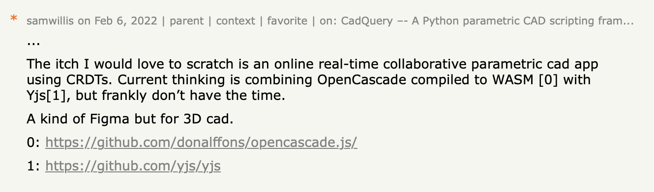
Four years ago I left a Hacker News comment describing a "real-time collaborative parametric CAD app using CRDTs... combining OpenCascade compiled to WASM with Yjs... a kind of Figma but for 3D CAD."
Before LLMs, this was completely out of my reach. Not just the building of it, but even doing the research to get started would have been a substantial undertaking. I had enough CAD background to know where to start, but I had nowhere near enough time to tackle any of it. I thought it was never going to be possible to disrupt the big CAD companies.
In late-2025 LLMs changed the equation. The simple truth is that it's now possible to build 'difficult things' at speed, on your own.
Over the holiday period I set out to see if, with the help of coding agents, I could build the editor I'd described on Hacker News.
When a telescope is being commissioned, there's a moment known as "first light", which is the first time a real image is captured. Even though the image might be blurry or imperfect, it proves that the whole system works end-to-end.
On December 20, 2025, I had my own "first light" moment. It confirmed not only that this project was actually possible, but also that the way we build has fundamentally changed forever.
In just two weeks, I built SolidType, a browser-based parametric CAD editor with sketching, a real B-Rep kernel, collaboration features such as presence and follow mode, and AI that can generate geometry through tool calls against the same model that humans edit. It's roughly 70k lines of TypeScript, and coding agents wrote essentially all of it.
This post isn't about agents replacing engineers, it's about a phase change in what's possible. Problems that required teams are now feasible for a solo developer, and projects that required months or years now take weeks. The constraint is no longer "can it be built?" but "can you design the right boundaries and feedback loops?"
This is part 1 of a two-part series. In this post, I wanted to share my build process and what I learned from the experience. In the next post, I'll focus on the infrastructure that made it possible.
Why CAD is a genuine test
CAD isn't a CRUD app. It isn't just about moving state around.
The established players — SolidWorks, Fusion 360, OnShape, and even FreeCAD — represent decades of accumulated engineering. The technical moats are all too real. A parametric CAD system has to solve a cluster of genuinely difficult problems:
Geometric kernel complexity: You need a boundary-representation (B-Rep) engine that can construct, intersect, trim, and Boolean-combine 3D solids reliably. This is computational geometry at industrial strength, and the established kernels — Parasolid, ACIS, OpenCascade — represent 20-30 years of continuous development.
Topological naming: When you extrude a sketch to create a box, fillet an edge, and then modify the original sketch, the system has to know which edge you intended it to reference — even though the underlying geometry has changed. This "persistent naming" problem has plagued open-source CAD for years. Get it wrong, and models will break every time you edit early features.
Constraint solving: Sketches need geometric constraints (parallel, perpendicular, coincident, distance, equal length) solved numerically in real-time as users drag geometry. This is a classic constraint satisfaction problem, where you're minimising residuals across a system of nonlinear equations while the user expects sub-50ms convergence. If you get the solver wrong then sketches fail to converge on a stable state resulting in entities jumping around, or they over-constrain trivially solvable geometry.
3D visualisation pipeline: The B-Rep geometry from the kernel needs to be meshed (tessellated into triangles), uploaded to the GPU, kept in sync with model changes, and handle the interactive selection of faces, edges, and vertices. This includes managing level-of-detail, handling large assemblies, and providing visual feedback for constraints and dimensions.
Parametric rebuild: The entire feature tree has to regenerate correctly when any parameter changes, maintaining dependencies and propagating updates without accumulating numerical errors or breaking references.
Distributed undo/redo: Undo needs to work across a tree of interdependent features, and when you add collaboration, it also needs to work across multiple users' edits in a mergeable document. This isn't "undo the last edit"; it's "undo my sketch change while preserving the extrude that depends on it."
Multi-user coordination: If you require collaboration, you need mergeable state, presence, and a way to handle concurrent edits to a complex hierarchical model without corrupting geometry.
These aren't API integration problems, but the kind of deeply technical challenges that create defensible moats around commercial CAD companies.
Yet, by the end of 2025, LLMs and the right infrastructure choices have made this a tractable problem.
How I worked: ChatGPT for thinking, Cursor for execution
My workflow was heavily LLM-driven, but it was in no way "vibes and prayers."
ChatGPT was primarily for research and design:
- Investigate approaches (FreeCAD's topological naming work, OCAF concepts, CAD literature)
- Produce design options and trade-offs
- To ask the annoying questions you generally avoid when you're working alone
- Generate structured interview prompts to extract a complete plan
Cursor was the execution engine:
- Take a plan and implement it
- Run tests and fix breakages
- Iterate on UI flows
- Do the refactors I'd otherwise postpone
Early on, I used ChatGPT to explore the problem space, then once I'd settled on a direction, I asked it to produce interview prompts: structured Q&A sessions that systematically extracted constraints before producing any code. I worked one question at a time, with no plan formed until there was enough context, before finally producing a single, coherent document.
This interview format worked because it forced the model to build up constraints before generating solutions. It was a way to ensure that all of my implicit assumptions were made explicit.
The overall pattern was text expansion: idea → bullets → spec → plan → code. The artefact needed here wasn't the chain-of-thought; it was the progressively more explicit constraints that another agent could then execute.
The architecture (a quick snapshot)
Before going into development details, here's the system's shape:
- CAD model: Lives in a Yjs document—mergeable, syncable, acts like a file format
- Kernel: OpenCascade compiled to WebAssembly via
opencascade.js—the mathematical engine that turns sketches and operations into solid 3D shapes - App data (workspaces, projects, metadata): Syncs via Postgres Sync into TanStack DB
- Presence, docs, AI sessions: Append-only Durable Streams—resumable event logs you can tail and replay
- AI orchestration: Runs client-side in a SharedWorker for durability across tab closes
One authoritative doc model, one robust kernel, one sync system for relational data, and one stream substrate for durable multi-user state.
Phase 1: Building a kernel from scratch (and why I stopped)
The project started with maximum ambition: build the geometric kernel from first principles.
The approach was classic kernel engineering: define a phased plan (math → geometry → topology → operations → naming → solver), keep everything test-driven, and ship narrow reliable slices rather than broader, fragile ones.
What emerged was real, but too narrow: I produced straight-line sketches, extrudes of straight-line profiles, co-planar and perpendicular cuts, and STL export suitable for 3D printing.
In December, I drew a wonky rectangle, hit Extrude, and watched it become a solid. That sounds trivial, but it meant invisible machinery had snapped into place: a sketch model that could be edited, a feature that consumes it, a rebuild that produces B-Rep geometry, a meshing pipeline that turns it into pixels, and a UI tight enough that the whole loop works without breaking the illusion.
It was enough to prove that the approach wasn't theoretical.
Then I tried face trimming. As soon as I attempted cuts at an angle, the geometry failed. The agent would generate plausible intersection code, and tests would pass for simple cases, but the 3D visualisation showed mangled faces. I spent a day trying to get the agent to solve it, and it turned into a time sink, as each "fix" solved one case but broke another.
This was the pivot point. I'd proven LLM-assisted kernel work could get surprisingly far, but continuing would dominate the project and pull it away from what I actually wanted to explore.
So I made a trade-off: use an established kernel and focus on the system around it instead.
The OpenCascade pivot: the trade-off that unlocked everything
OpenCascade (via opencascade.js) was the obvious choice. It's robust enough to stand on, has decades of lessons learned, and it ships as WebAssembly. Moving to it was a big pivot, but the process was significantly smoother than I expected.
OpenCascade has been around since the 1990s. Patterns for using it are all over the internet, and have therefore been included in training data. Cursor "just knew" how to wire it up, and the library worked without issue.
After changing the kernel to OpenCascade, feature implementation accelerated dramatically, and operations that would have taken days of debugging intersection math (revolve, Boolean unions, fillets) became afternoon tasks, all because OpenCascade handles the geometric complexity.
Because that knowledge of how to use mature libraries exists in the model's training corpus, there's no requirement to teach it from scratch.
Plan-driven development: how agents execute at scale
Once the architecture stabilised, the project changed character; moving from "research prototype" to "execute a roadmap."
I wrote what I called "The Big Plan": a phase-by-phase set of documents describing vertical slices. The sequencing here was deliberate: Line sketches → Extrude → Cut → Revolve → Constraints → Arcs → Selection & rebuild gating → Properties → Sketch-on-face → Booleans → Export → AI infrastructure & tools.
This plan acted like a contract, decomposing work into steps an agent could complete. It pinned decisions early to avoid schema churn, and made "done" explicit (tests, UI workflow, docs updated).
The discipline lived in written plans (phases, definitions of done, explicit invariants), tests (especially around kernel-style logic), explicit boundaries (doc model vs kernel vs UI vs worker), tight feedback loops (tests early, manual UX loops, targeted debugging), and commit messages as accountability.
Example: when implementing sketch constraints, I insisted on test coverage before UI work. The agent wrote comprehensive unit tests for constraint solving, catching edge cases that would have been painful to debug through the UI later.
This was collaborative engineering where the collaborator happens to be an LLM, it was not vibe coding.
Engineering discipline doesn't disappear — it only shifts
I read very little code, choosing instead to work at 10k feet: Is the system well-structured? Are responsibilities clean? Is the plan being followed? Are we staying inside constraints?
I used the LLM as both mirror and advisor: to explain the architecture back to me, to justify trade-offs, to propose safer options, and to critique implementation against docs and invariants.
The human role changed. Instead of writing code, I was:
- Designing constraints and boundaries
- Evaluating structural decisions
- Maintaining explicit invariants
- Running tight feedback loops
- Ensuring the plan gets followed
The agents bring speed and throughput, the user bring architecture and judgment.
Enabling collaboration
As a minimum bar, I wanted shared edits visible on multiple users' screens, instantly showing when another user makes a change. The extended goal was presence, cursors, and follow mode to enable that human connection with your collaborators.
It came together quickly because I didn't treat collaboration as a single feature to add at the end. Instead, I recognized that SolidType has two fundamentally different kinds of state:
Database-shaped app state (workspaces, projects, permissions, file tree) wants relational sync.
Document-shaped CAD state (the model itself) wants an append-only, resumable log that fans out to multiple clients.
This maps cleanly onto infrastructure:
- ElectricSQL + TanStack DB: Live, query-driven sync from Postgres. The surrounding "app" behaves like a shared system by default.
- Durable Streams: The CAD model lives in a Yjs document, and Durable Streams gives it durable event logs you can tail, resume after disconnects, and share across tabs and users.
Once these layers were in place, "collaboration features" stopped being special cases. Presence is just another stream, as is follow mode; even AI sessions are just another stream. Same coordination mechanism, no ad-hoc plumbing.
This is where "infrastructure that gets out of the way" becomes real. CAD is complex and I was doing weird things, like AI-generating geometry in a multi-user environment. I wanted to spend time on that, not contorting a sync framework.
I'm writing a companion post on the sync architecture that will be published soon
Integrating AI with Durable Streams
People assume the hard part of "AI integration" is writing tool definitions, but that wasn't my experience. The tool calls were easy, but the difficulty was actually everything around them: making an AI session durable, resumable, multi-user, and observable.
That's where Durable Streams comes in.
Durable Streams turns an AI session into a resumable, append-only log. Not a websocket conversation, or an in-memory state, but a log you can tail, resume after disconnects, share across users, and treat as a first-class collaborative object.
Once you have that log, you get a useful property: you can run tool execution in multiple environments without changing the session model.
- A browser tab can stream events and render UI
- Another tab can attach later and see the same session
- An agent runtime can execute tools wherever makes sense and write results back into the same stream
In SolidType, the agent runtime lives in a SharedWorker for a specific reason: it needs its own long-running copy of the CAD kernel (loading OpenCascade WASM takes 2-3 seconds), it needs low-latency tool execution close to the UI, and it needs to survive tabs closing so that AI sessions don't get interrupted.
But that's an implementation choice. The runtime could just as easily be on a server and the session would work the same way, because the Durable Stream is the coordination layer.
The first moment where it felt "real" wasn't from a clever response, but something much more concrete: I typed, "Draw a sketch on the XY plane with a circle of radius 20mm" and it did it, producing geometry that I could see, edit, undo, and share. It wasn't a description, or code; it was actual CAD primitives in the model, indistinguishable from manual creation.
The full pattern of how AI sessions work with Durable Streams, how tools execute against the same model humans edit, and why this enables collaborative AI, will be covered in detail in Part 2.
The reality check: CSS and taste
The most common failure mode in this build was CSS.
The agent got close but never quite hit the right mark. The only code that I found myself consistently adjusted was styling: spacing, alignment, small usability details – the final 10-20% that makes something feel intentional.
Agents excel at architecture and throughput when they have constraints and tests, but UI polish is taste, and taste requires significant context.
There were two loops:
- Interactive: paste screenshots, refine "how it should feel," iterate on layout
- Rare hands-on-keyboard: when the agent couldn't make the behaviour work
There was one case where the agent really wanted flexbox for everything, and the simplest solution was actually a float. That was one of very few times I had to write code directly.
What's next: real CAD milestones
If there's a "this is genuinely real" milestone from here, it's external references in sketches: sketches constrained to existing geometry.
Concrete example: sketch on a face that references an edge of a hole.
This forces you to solve stable references and projection semantics properly; and it brings topological naming and rebuild stability back to centre stage, which is where they belong.
After this comes the truly massive step: making AI interactive in a loop – understanding geometry, working toward goals, and iterating. That's for later, though, and it's an entirely different scale of problem.
One practical route is giving the model eyes. The current system has strong symbolic context (feature tree, parameters, IDs), but CAD is visual. Feeding images of the model back into the LLM gives it an extra channel for "what the user sees”, which is exactly what you need for iteration and catching mistakes.
The shift
This project validates a number of fundamental truths about where we are right now:
LLMs can build genuinely complex systems end-to-end. Not "can they write a React component?" or "can they build a todo app?", but "can they navigate the dependency graph of a real geometric kernel, implement parametric rebuild logic, wire up constraint solvers, and produce something that actually works?" This project produced a working CAD editor with real geometry, real collaboration, and real AI integration. That would have been science fiction two years ago.
Established tech compounds that capability. OpenCascade, Yjs, standard web APIs—the agent understood these immediately because patterns for using them exist in training data. Newer tools like TanStack DB that model their APIs on existing conventions work well for the same reason. The model already knows how to use mature libraries.
Collaboration and AI want the same primitives. Shared state, resumable logs, fork/merge semantics. Once you treat an AI agent as another user, the infrastructure requirements converge. This isn't a coincidence—it's a design pattern.
Infrastructure that gets out of the way is leverage, not luxury. CAD is already difficult, and I didn't want to have to also fight my sync layer, my database, my collaboration primitives, or my AI orchestration. I wanted those parts to be boring—not because they're simple, but because they're solved problems with clear patterns.
This was also a deliberate dogfooding exercise. I'm building infrastructure at ElectricSQL, and so I wanted an "in-the-shoes" project: the kind of complex, stateful, multi-user application that our users actually build.
In all of this, there was a specific bar to clear: Figma is the textbook example of real-time collaborative editing done correctly. Multiple users, live cursors, presence, conflict-free merging – it just works. The question was whether I could achieve that level of smoothness for 3D CAD, which is orders of magnitude more stateful and complex than 2D graphics.
This project obviously doesn’t have Figma's scale or polish – this was a week of my time, and not the output of a decade-old company – but it needed to have the same feel of smooth, real-time, multiplayer editing that doesn't constantly remind you that it's distributed.
If the stack couldn't handle that without constant friction, then something was wrong.
The bottleneck shifted. A single developer with LLMs can now tackle the genuinely hard parts — geometry kernels, constraint solvers, parametric rebuilds. With infrastructure tailored to modern application patterns, the coordination layer stops being a constraint. The infrastructure parts got out of the way, leaving the CAD-specific problems (geometry, constraints, stability) as the 'difficult bit'. The pace of development fundamentally changes.
2026 will see more of these projects. Not just CAD — in every domain with real technical depth. Finance, biotech, robotics, infrastructure. The pattern is the same: combine capable LLMs with infrastructure that gets out of the way, maintain tight feedback loops, and build the rails.
If you're building something complex in 2026, the question isn't "can an agent write code?"
The question is: can you design the constraints, feedback loops, and boundaries so the agent keeps making correct progress?
That's where the discipline lives now. Plans, tests, boundaries, explicit invariants, tight feedback loops. The agent brings speed and throughput; you bring architecture and judgment.
Build the rails. The agent will run on them.
Want the technical deep-dive? Stay tuned, I'm writing a companion post on the infrastructure that made this possible: covering the sync architecture, Durable Streams implementation, AI orchestration in a SharedWorker, and code patterns worth stealing.