Theory
of Operation:
The Quarter Shrinker uses a technique called high-velocity
electromagnetic forming.
This is sometimes called "magneforming" or magnetic pulse forming, and
is a high-energy-rate metal forming process. High-energy rate
processes apply a large amount of energy to an object for a very short
period of time. The technique was originally
developed by the aerospace industry in conjunction with NASA, and was commercialized by Aerovox,
Grumman, and Maxwell Technologies (now a subsidiary of General Atomics). EM forming uses pulsed power technology to quickly discharge high-energy discharge capacitors through a coil of wire to generate a brief, but extremely powerful, rapidly-changing magnetic field to re-shape metals inside or near the coil. Although electromagnetic forming works best with metals that have
good electrical conductivity (such
as copper, silver, or aluminum), it also works to a limited extent
with poorer-conducting metals or alloys such as nickel or steel.

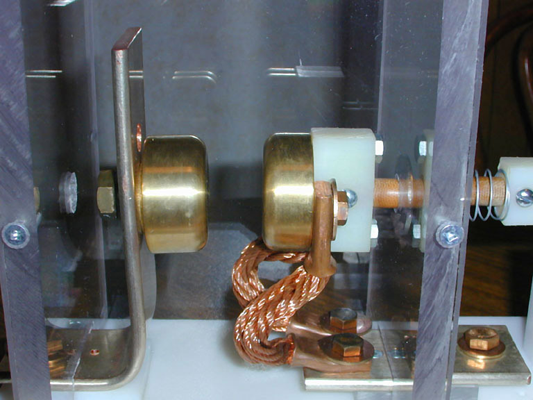
Once the spark gap fires, current climbs in the work coil at a rate that can approach five billion amperes per second. As the work coil current increases, it creates a rapidly increasing magnetic field inside the work coil. The resonant frequency of the resulting LC circuit (the capacitor bank and the combined inductance of the work coil and the rest of the system) ranges between 7.8 and 10 kilohertz (kHz) depending on the diameter of the coin and the work coil. Through electromagnetic induction ("transformer action"), a huge circulating alternating current is induced within the coin. However, due to skin effect, the induced current in the coin is forced to flow only through the outermost rim of the coin, forming a ring of current that's only about 1/20 of an inch thick. B
ecause of Lenz's Law, the magnetic fields of the coin and work coil strongly oppose each other, resulting in a tremendous repulsion force (Lorentz force) between the work coil and the outer rim of the coin. The repulsion force is directly proportional to the initial energy stored in the capacitor bank. Since the capacitor bank's stored energy is proportional to the square of its voltage, doubling the capacitor voltage quadruples the peak magnetic force.We typically use capacitor discharges with initial energies between 2,000 to 9,600 joules
(watt-seconds). Since the energy is discharged within 20-40
millionths of a second, the peak power
briefly approaches the electrical power consumed by a large city. The repulsion forces between the
work coil and the coin create radial compressive forces that
easily overcome
the yield strength
of the alloys in the coin, causing the coin's diameter to shrink. A
5,000 joule pulse reduces a US clad quarter to the diameter of a
dime. Simultaneously, powerful outward forces, sometimes called "magnetic pressure",
cause the work coil to explode
in a potentially lethal shower of copper shrapnel. Axial magnetic forces
also smash the wire turns together while the coil is simultaneously
expanded in diameter.
The magnetic forces acting on the winding are always
in a direction that tend to increase the work coil's inductance - increasing diameter and reducing the coil winding length.
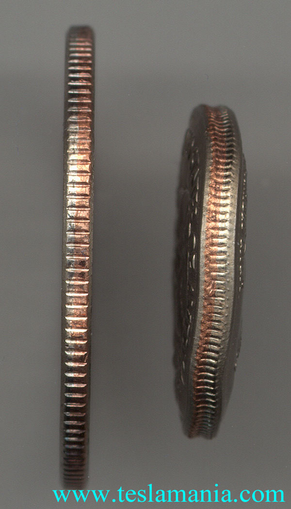
During the shrinking process, the coin behaves like a short-circuited secondary in a 10:1 step down transformer. The peak current circulating within the outer rim of the coin may approach a million amperes! A US clad quarter is typically reduced from an initial diameter of 0.955" to approximately 0.650" within 36 millionths of a second. The magnetic forces cause the coin's diameter to shrink at a average rate exceeding 480 miles per hour. In US clad coins, most of the induced current actually flows within the pure-copper center layer of the clad sandwich rather than through the poorer-conducting copper-nickel alloy cladding layers. This causes the copper center layer to shrink a more than the outermost layers, leading to an "Oreo cookie" effect on the shrunken coin. The coin also becomes thicker as it shrinks in diameter. Despite the radical changes to the coin, its mass, volume, and density all remain the same after shrinking. The Oreo cookie and thickening effects can be easily seen in the following edge-on image of a normal-size and shrunken US quarter. The slight waviness in the shrunken coin is due to slight force imbalances including variations in coin thickness from the coin's surface features, and dynamic force imbalances as the work coil changes shape before exploding. This short video clip from the Florida State University National High Magnetic Field Laboratory provides an excellent explanation and demonstration of quarter shrinking. In their demonstration, they use #14 AWG magnet wire for their work coils. We use #10 - #14 AWG wire on our work coils depending on the size of the coin we're going to shrink.
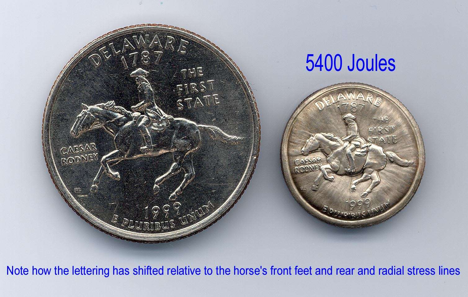
In clad coins, as the copper core layer shrinks, the outer cladding
layers of the coin are pulled along for the ride, similar to the way
continental drift is thought to move continents in
the Earth's crust. This sometimes leads to "collisions" between various surface
features, and one feature may actually plow underneath another!
For example, note how some of the lettering on
the Delaware
quarter below have shifted so that they become partially obscured by various
parts of the horse.
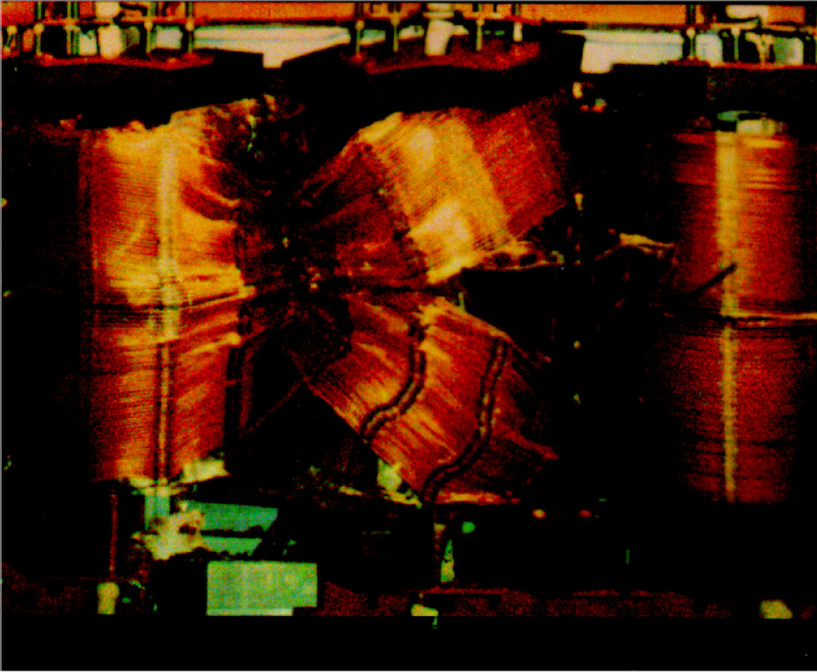
Similar effects of intense magnetic forces
are sometimes seen on a much larger scale: For example, during
accidental short circuits in electrical power systems, repulsion forces
between primary and secondary windings inside large substation power
transformers or between bus bars can
literally tear the windings apart or rip bus bars from their mounting insulators.
As the
coin shrinks similar, but opposite, forces act upon the work coil's windings.
Magnetic pressure rapidly expands and stretches the copper wire in the work
coil. The film insulation peels off the wire since it can't stretch as
much as the copper! The wire coil "rapidly disassembles" (explodes!), and
fragments of the coil are blown
outward with the force of a small bomb. Small coil fragments
have been measured with velocities of up to 5,000 fps (>3400 mph, or greater than Mach
4), so the work coil must be
safely contained within a heavy blast shield. Our blast shield is made from Lexan
polycarbonate, the same material that's used
to make bulletproof windows. Regions of the blast shield that are in the direct
path of exploding coil fragments are further reinforced with steel
armor plates. Once the work coil disintegrates, any residual energy in the
system is dissipated in a ball of white-hot plasma.
The Quarter Shrinker is designed so that any residual voltage on the
capacitor bank is safely dissipated by a bank of high-power wirewound
resistors. The system is triggered from about 10 feet away from
a remote control box. I've found (the hard way!) that 8,000 Joules is
about the maximum energy I can repeatedly use without running the risk of
fracturing the Lexan walls from the shock wave. When slammed by a
high-intensity shock wave, Lexan does indeed shatter - I've got the
pieces to prove it! Other
experimenters
(Rob Stephens, Bill Emery, Phillip Rembold, Ross Overstreet, Brian
Basura, Joe DiPrima, and Ed Wingate) have resorted to using 100% steel enclosures
when running at higher power
levels.
Adding strategically-placed steel plates has stopped our Lexan blast
shield from
fracturing. We've found that AR400 steel plates (also used for armor in some miltary vehicles)
are well suited to surviving repetitive bombardment from supersonic
coil shrapnel. But even these must be periodically replaced after a couple
thousand shots.
Following is a video made by our friends Physics Girl and Joe DiPrima which describes in detail just how coin shrinking actually works. Included is a short segment of some high speed video that was captured by the amateur scientists at Hackerbot Labs (Seattle, WA). By using a special 180,000 frame/second camera they were able to capture a sequence of images of coins AS THEY WERE BEING SHRUNK (video time 1:02 - 1:24). Because the shrinking process occurs so rapidly, the actual "shrinkage" is only seen during a few consecutive frames - about 40 millionths of a second in real time.
Our Results:
The largest coin we've ever shrunk was a US Silver Eagle, a pure silver coin that was reduced from 1.6" in diameter to 1.3" after a 6300 Joule shot. At similar energies, a Morgan silver dollar is reduced from about 1.5" to 1.25" in diameter, and a clad Kennedy half dollar is reduced to the diameter of a US Quarter. At 5,000 joules, US clad quarters shrink to the diameter of a dime. A few years ago, physicist Dr. Tim Koeth and I took various measurements of work coil current during the shrinking process. These showed that the work coil consistently failed shortly after the first current peak. Fortunately, virtually all of the coin's shrinkage has occurred by this time. Disintegration of the coil helps to reduce voltage reversals that could damage, and eventually destroy, the energy discharge capacitors. The combination of high peak currents and oscillatory discharges is extremely demanding on capacitors. Because of premature failures with earlier GE pulse capacitors, the current system uses low inductance Maxwell (now General Atomics Energy Products - GAEP) pulse capacitors that are designed to safely cope with this abuse. While the original GE capacitors began failing after only 50 - 100 shots, the trusty Maxwell capacitors have withstood well over 7,000 shots with nary a whimper.
Examination of the coil fragments show that the wire has been substantially stretched (#10 AWG looks like #14 AWG afterwards), it becomes strongly work hardened, and it has periodically "pinched" regions and kinks caused by the copper being stressed far beyond its yield strength by the ultrastrong pulsed magnetic field. Many fragments are less than 1/4" long, and all pieces show evidence of tensile fracture at the ends. Since the wire's insulation gets blown off, most fragments are bare copper. The wire often also shows signs of localized melting on the innermost surface of the solenoid due to "current bunching" from the combination of skin effect and proximity effect.
The
Quarter
Shrinker works very well on clad dimes, quarters, half dollars,
Eisenhower, silver Morgan and Peace Dollars, Susan B. Anthony,
Sacagawea, small Presidential dollars, and many foreign coins.
It works less well with nickel and nickel-copper coins, and
it has virtually no effect on plated steel coins. It also works well with
older
bronze and copper-zinc alloy pennies. However, since mid-1982, US
pennies
have been made using a zinc core with a thin copper overcoat. During
shrinking,
the thin copper layer vaporizes and the zinc core melts, leaving an
unrecognizable
disk of molten zinc accompanied by a messy shower of zinc globules
throughout the
blast chamber.
Because of the greater hardness and much poorer electrical conductivity
of nickel-copper alloys, the shrinking process doesn't work as well
with US
nickels, shrinking them by only about 10% even at 6,300 Joules. Larger
copper-nickel coins, such as the UK Churchill Crown, seem to be almost
impervious to shrinking even at 6,300 Joules - this coin is as tough as its namesake!
A shrunken coin weighs exactly the same as it did before shrinking. As the coin's diameter shrinks, it becomes correspondingly thicker, but its volume and density remain the same. Bimetallic foreign coins (with rings and centers made from different alloys) often show different degrees of shrinkage based upon the individual electrical conductivity and hardness of the respective alloys. In some cases, the center portion shrinks a bit more, loosening or sometimes even freeing it from the outer ring. Complete separation occurs with older Mexican, UK, and French bimetallic coins, and with newer Two Euro bimetallic coins.
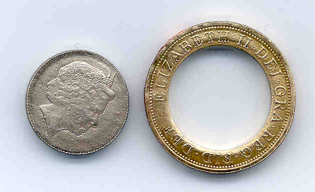
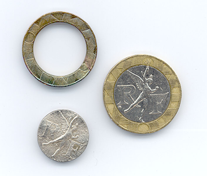
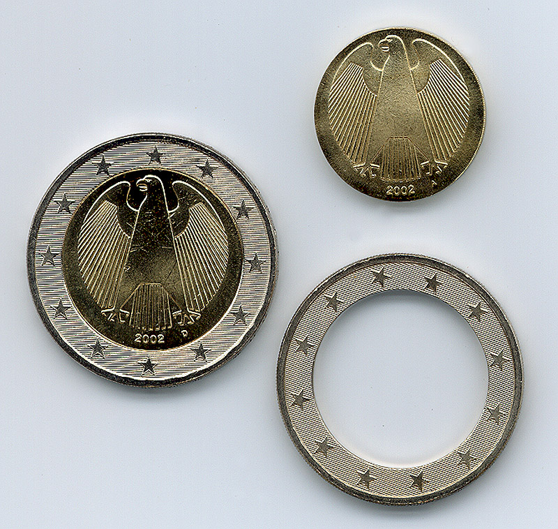
Because
of
the extremely high discharge currents
and fast current rise times, capacitors rated for energy discharge applications must be designed
to
have high mechanical strength and very low inductance. They use special internal construction
techniques to
safely handle mechanical stresses created by strong magnetic and electrostatic forces
during fast, high-current discharges. When we first began coin shrinking, we used some GE
energy discharge capacitors that were simply not constructed for this type of abuse,
and unbeknownst to us, magnetic forces began tearing them apart during every shot. One
unit actually
suffered an internal electrical explosion that ruptured its metal
case, causing it to hemorrhage stinky, arc-blackened capacitor oil and aluminum foil fragments all over the floor.
The wife was not amused! Our Maxwell energy discharge
capacitors have proven to be true
"Timex's" of the pulsed power world - they continue to "take a lickin' and keep on
tickin'".
2/4/14
Update - One of our Maxwell capacitors finally failed. While charging
the bank, a muffled bang was heard, the bank voltage
abruptly plunged from about 8 kV to zero, and the mains fuse in the
power controller blew. The problem was traced to a catastrophic failure of one of the Maxwell
capacitors. The failing capacitor developed an internal short
circuit,
and all of the stored energy in the capacitor bank (~4.5 kJ) was
abruptly dumped into the internal fault. Fortunately, the heavy steel
case didn't rupture, so I was spared cleaning up several gallons
of castor oil. This capacitor, and an identical mate, had survived over
6,000 "shots" in the quarter shrinker, so I'm very satisfied with its
performance. Further research determined that the root cause of the
failure was not lifetime-related, but was due to an extended period of
abnormally low temperatures. These capacitors use a combination of kraft
paper and
castor oil for the dielectric system that separates the foil plates. The
Quarter Shrinker resides in an unheated patio.
Although cold temperatures had not been a problem during previous
winters, 2014
was abnormally cold in the Chicago area. When the capacitor's internal temperature fell below -10C
(14F), the castor oil began to partially solidify. As castor oil
solidifies, its dielectric constant drops from 4.7 to about 2.2. During solidification, small
amounts of dissolved water (that were previously harmlessly in
solution), were driven out of solution and absorbed by the kraft paper.
The reduced
dielectric constant increased the voltage
stress on the kraft paper dielectric while the absorbed water
simultaneously reduced its electrical strength. The result was sudden
dielectric failure and catastrophic short-circuiting of the capacitor.
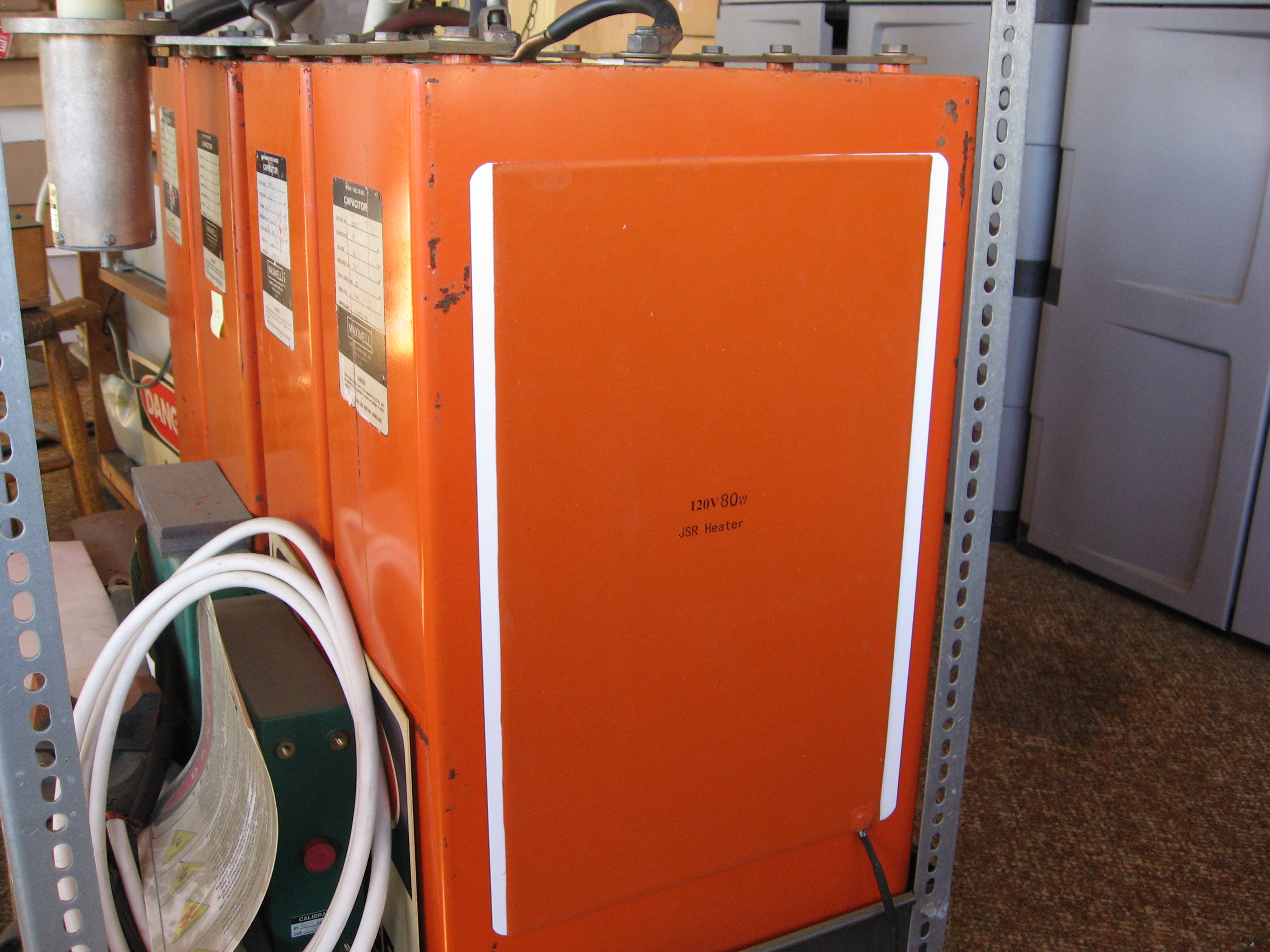
We've subsequently installed flexible silicone electrical
heating elements to the
sides of the capacitors to always keep them toasty
(above 40F) during even the coldest days. This will prevent any future
freezing problems. With the new heaters in place, the winters of 2015 -
2018 were nicely uneventful.
Can Crushing:
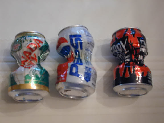
A larger diameter 3-turn work coil, operating at lower power levels, is used to crush aluminum cans. An aluminum soft drink can ends up looking like an hourglass as the center is shrunk to about half its original diameter. During can crushing, the coil does not disintegrate due to its more massive design (#4 AWG solid copper wire) and because the system is fired using lower energy levels than coin crushing. At higher power levels, the can is ripped apart from the combination of the air inside the can suddenly being compressed, and heat-softening of the can from the induced currents. Can crushing also works with steel cans, but the can undergoes greater heating and reduced shrinkage because of steel's lower electrical conductivity. The "skin depth" in steel is also much smaller due to its ferromagnetic properties. Since the work coil is not destroyed during can crushing, the capacitor bank and spark gap are more heavily stressed by the oscillatory ("ringing") discharge. The capacitor bank voltage must be reduced to so that the ~100% voltage reversals don't overstress the pulse capacitors' dielectric system. Since most of the capacitor bank's initial energy ends up being dissipated as heat in the spark gap, can crushing also causes significant heating and erosion of the electrodes in the high voltage switch.
Is Wire Fragmentation Consistent with EM Field Theory?
Copper wire fragments from the work coil clearly indicate that the wire has been subjected to large tensile stresses. Most of the observed effects on the wire can be explained by hoop stresses created by the combination of magnetic pressure within the work coil solenoid, Lenz's Law repulsion between the coil and the coin, and periodic conductor necking. The latter occurs when magnetic pinch forces are sufficient to cause the conductor to behave as though it were a conductive fluid. Because of pinch instabilities, the wire becomes periodically pinched off and broken. However, there is also a curious ridge which shows up under microscopic examination of the coil fragments that may hint of other effects as well. This artifact was first noticed by Richard Hull of the Tesla Coil Builders of Richmond, Virginia (TCBOR) when reviewing similar wire fragments from another researcher (Jim Goss). It seems that when an extremely high current flows through a solid or liquid metallic conductor, certain effects begin to appear which may not be fully explained by existing EM field theory and Lorentz forces.
One very interesting example involves forcing a very large
current pulse very quickly through a straight piece of wire. Under
appropriate
conditions, the wire does not melt or explode. Instead, it fractures
into
a series of roughly equal length fragments, with each fragment showing
unmistakable
evidence of tensile failure. Following is an example (from Jan Nasilowski, (1964) "Unduloids and Striated Disintegration of Wires".
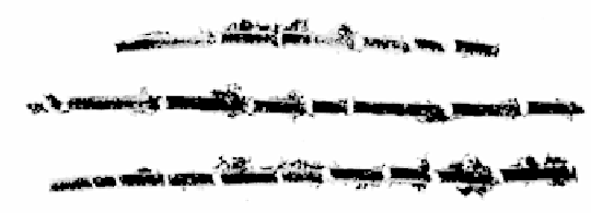
Each segment was literally pulled apart from neighboring fragments with little or no evidence of necking or melting. Clearly large tensile forces were set up within the wire during the brief time that the large current flowed. But, per existing EM theory, no tensile forces should exist, implying that the current theory of how Lorentz forces act on metallic conductors may be incorrect!
A father and son team of physicists,
Dr.'s Peter and Neal Graneau (coauthors of "Newtonian Electrodynamics"
and "Newton Versus Einstein")
theorize that internally developed "Ampere' tensile forces" may account
for the observed behavior of this, and other high-current experiments.
While Ampere' tensile forces are predicted by classical electromagnetic
theory, they have long been removed from all modern textbooks, being replaced
instead by modern field theory and Lorentz forces. Interestingly, even though Ampere' forces
are no longer an accepted part of current EM theory, their existence appears to be experimentally
verifiable in exploding wires or high DC current flow within molten metals (such as aluminum refining).
In their books, the Graneau's provide many thought-provoking
experiments
that appear to support Ampere' Tension forces. More recently, other
scientists have proposed that high-current wire fragmentation may actually be
caused by a combination of flexural
vibrations and thermal shock. However, we suspect that the jury is
still out on this issue, and its an area that's ripe for
additional research and experimentation.
Isn't Mutilating Money a Federal Offense?
US Federal law specifically forbids the "fraudulent mutilation, diminution, and falsification of coins" (see US Code, Title 18 - Crimes and Criminal Procedure, Part I - Crimes, Chapter 17 - Coins and Currency, Paragraph 331). However, the key word is Fraudulent. Although it recently became illegal to melt pennies or nickels or to export them to reclaim their value as scrap metal, you can otherwise do pretty much anything to US coins as long as you don't alter them with an intent to defraud. This includes squashing them on railroad tracks, flattening them into elongated souvenirs at tourist traps... or crushing them with powerful electromagnetic fields. I take great pains to tell folks exactly what they are receiving and how the process was accomplished. So vending machines in tourist traps that squash pennies into elongated souvenirs or "funny" stamped pennies with Lincoln smoking a cigar are legal (although the coins can't be used as currency anymore). In an opinion letter, folks at the US Mint "frown on the despicable practice" of altering coins, but they agree that it is quite legal to shrink coins. Note that this is not always the case within other countries! For example, in the UK and Australia, defacing the Queen's image on a coin may be considered a punishable offense.
Paragraph
332
deals with debasement of coins; alteration of official scales,
or embezzlement of metals. Since most of the coins we shrink are made
from base metals, this section does not apply. However, since the density, metal
content, and weight remain unaltered during the shrinking process, coin
shrinking is legal even when applied to bullion coins made from precious metals,
and most larger gold and silver coins shrink quite nicely. HOWEVER, shrinking US paper money is indeed
illegal. Even though we are aware of a couple of chemical processes that
can shrink dollar bills to about half their original size, we do not
make or
sell "shrunken dollar bills", since defacing paper currency is indeed
illegal.
See Paragraph 333 for details.
Are you the nut who invented this device?
No, it wasn't this nut! We just perfected the technique. For the history of coin shrinking, check out The Known History of "Quarter Shrinking"
There s always a hole in theories somewhere, if you look close enough
Mark Twain, Tom Sawyer Abroad , Charles L. Webster & Co., 1894
Following are various references for the serious researcher. As many are out of print, you may also wish to check the "Out of Print Books Information" and "In Print Book Sources" sections of the Links Page, or check with your local technical college library system.
A. Electromagnetic Metal Forming and Magneto-Solid Mechanics:
1. ASM, "Metals Handbook, 8th Edition, Volume 4, Forming", American Society for Metals
- see section on Electromagnetic Forming (out of print)
2. Wilson, Frank W., ed., "High Velocity Forming of Metals", ASTME,
Prentice-Hall, 1964, 188 pages (out of print)
3. Bruno, E. J., ed., "High Velocity Forming of Metals", Revised, edition,
ASTME, 1968, 227 pages (out of print)
4. NASA, "High-Velocity Metalworking, a Survey, SP-5062", National Aeronautics
and Space Administration, 1967, 188 pages (out of print)
5. Moon, Francis C., "Magneto-Solid Mechanics", John Wiley & Sons, 1984, ISBN 0471885363, 436 pages (out of print)
6. Murr, L. E., Meyers, M. A., ed., et al, "Metallurgical Applications
of Shock-Wave & High-Strain-Rate Phenomena", Marcel Dekker, 1986,
1136 pages, ISBN 0824776127 (in print)
7. "Pulsed Magnet Crimping" by Fred Niell, straightforward explanation of magnetic forming (fairly technical, written by a physicist)
B. Capacitor Discharges, High Magnetic Fields, Pulsed Power/Switching, and Exploding Wires:
1. Frungel, F., "High Speed Pulse Technology", Vol. 3, Academic Press,
1976, 498 pages (Capacitor Discharge Engineering, out of print)
2. Schaefer, Gerhard, "Gas Discharge Closing Switches", Plenum, 1991,
569 pages (out of print)
3. Martin, T. H., et al, "J. C. Martin on Pulsed Power", Plenum, 1996,
546 pages (out of print)
4. Knoepfel, H., "Pulsed High Magnetic Fields; Physical Effects &
Generation ", Elsevier, 1970, 372 pages (out of print)
5. Fowler, C. M., Caird, Erickson, "Megagauss Technology and Pulsed
Power Applications", Plenum; 1987; 879 pages (out of print)
6. Vitkovitsky, Ihor, "High Power Switching", Van Nostrand Reinhold,
1987, 304 pages
(out of print)
7. Pai, S. T, & Zhang, Q., "Introduction to High Power Pulse Technology",
World Scientific, 1995, 307 pages (in print)
8. Sarjeant, W. J. & Dollinger, Richard E., "High Power Electronics",
Tab Professional & Reference Books, 1989, 392 pages (out of print)
9. Shneerson, G. A., "Fields & Transients in Superhigh Pulse Current
Devices", Nova Science, 1997, 561 pages (out of print)
10. Parkinson, David H., Mulhall, Brian E., "The Generation of High
Magnetic Fields", Plenum, 1967, 165 pages (out of print)
11. Chace, W. G., Moore, H. K, "Exploding Wires", Volume 1, Plenum, 1959, 373 pages (out of print)
12. Chace, W. G., Moore, H. K, "Exploding Wires", Volume 2, Plenum, 1962, 321 pages (out of print)
13. Chace, W. G., Moore, H. K, "Exploding Wires", Volume 3, Plenum, 1964, 410 pages (out of print)
14. Chace, W. G., Moore, H. K, "Exploding Wires", Volume 4, Plenum, 1967, 348 pages (out of print)
15. Mesyats, Gennady A., "Pulsed Power", Springer, 2004, 568 pages, ISBN 0306486531
16. Nasilowski, J. (1964) "Unduloids and Striated Disintegration of
Wires", in Chase, W.G. and Moore, H.K., Eds., "Exploding Wires", Volume
3, Plenum, New York, pp295-313
C. Special Reading for
those wishing to delve deeper into some more "interesting" areas of EM
Field Theory and Wire Fragmentation:
1. Graneau, Peter & Neal, "Newtonian Electrodynamics", World Scientific,
1996, 288 pages (in print)
2. Graneau, Peter & Neal, "Newton Versus Einstein, How Matter Interacts
with Matter", Carlton Press, 1993, 219 pages (in print)
3. Jefimenko, Oleg, "Causality, Electromagnetic Induction, and Gravitation",
Electret Scientific, 1992, 180 pages (in print)
4. Lukyanov, A., Molokov, S., "Why High Pulsed Currents Shatter Metal Wires?",
Pulsed Power Plasma Science, 2001, Digest of Technical Papers, Volume 2,
pages 1599-1602
5. Lukyanov, A., Molokov, S., Allen, J. E., Wall, D., "The Role of Flexural
Vibrations in the Wire Fragmentation", Pulsed Power 2000, IEE Symposium ,
pages 36/1 -36/4
6. Wall, D. P., Allen, J. E., Molokov, S., "The Fragmentation of Wires
by Pulsed Currents: Beyond the First Fracture", Journal of Physics D: Applied Physics.
36 (2003) 2757 2766
D. Web-Accessible Sources of Information about proposed "Ampere' tension" forces:
https://dflund.se/~snorkelf/Longitudinal/Slutdok.html