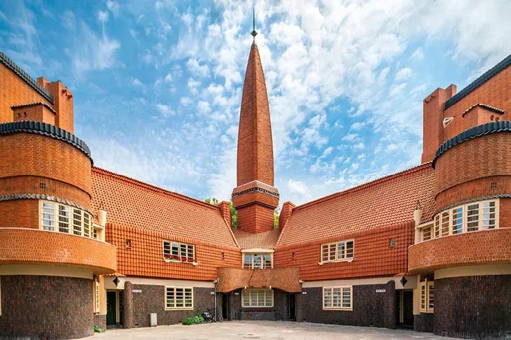
How much have you thought about the buildings around you? The style, material, patterns, architecture? Depending on where you live, you may be fortunate enough to admire these traits or be sadly underwhelmed. Lucky for me, living in Amsterdam, there is no shortage of beautifully designed architecture to draw inspiration from. Even in Amsterdam, rising labor, material, and land costs created financial pressures that gave way to reduced aesthetics and design, though usually for good reason to enable more housing to be built. Still, it doesn’t need to be this way.
Famous Buildings in Amsterdam


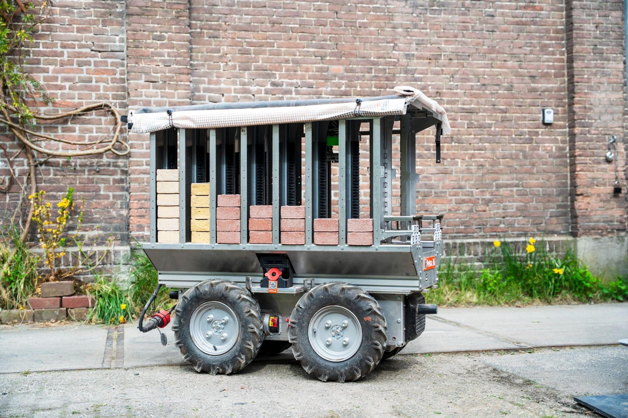
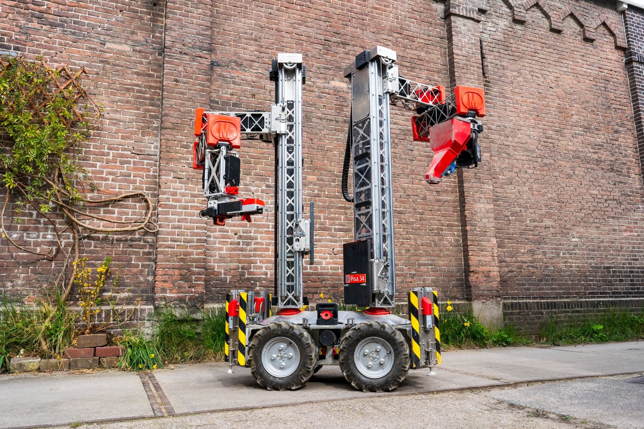
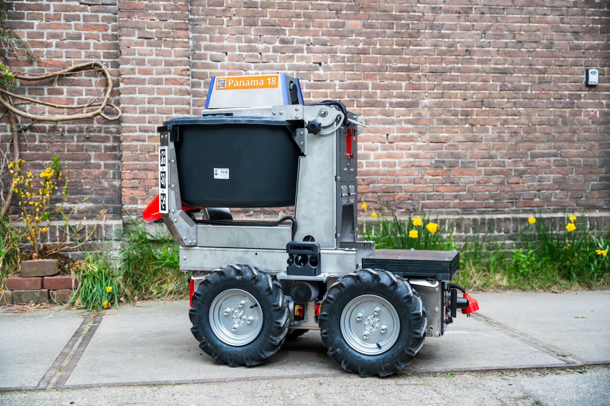
Here at Monumental, we aim to not only reduce the cost of construction but also enable competitive and aesthetically pleasing construction. To accomplish this, Monumental aims to use robots to solve worker shortages and simplify building ornate buildings. There are 3 robots: Pisa (the brick layer), Petra (the brick supplier), and Panama (the mortar supplier). Together, these robots form a fleet system that autonomously constructs brick walls.
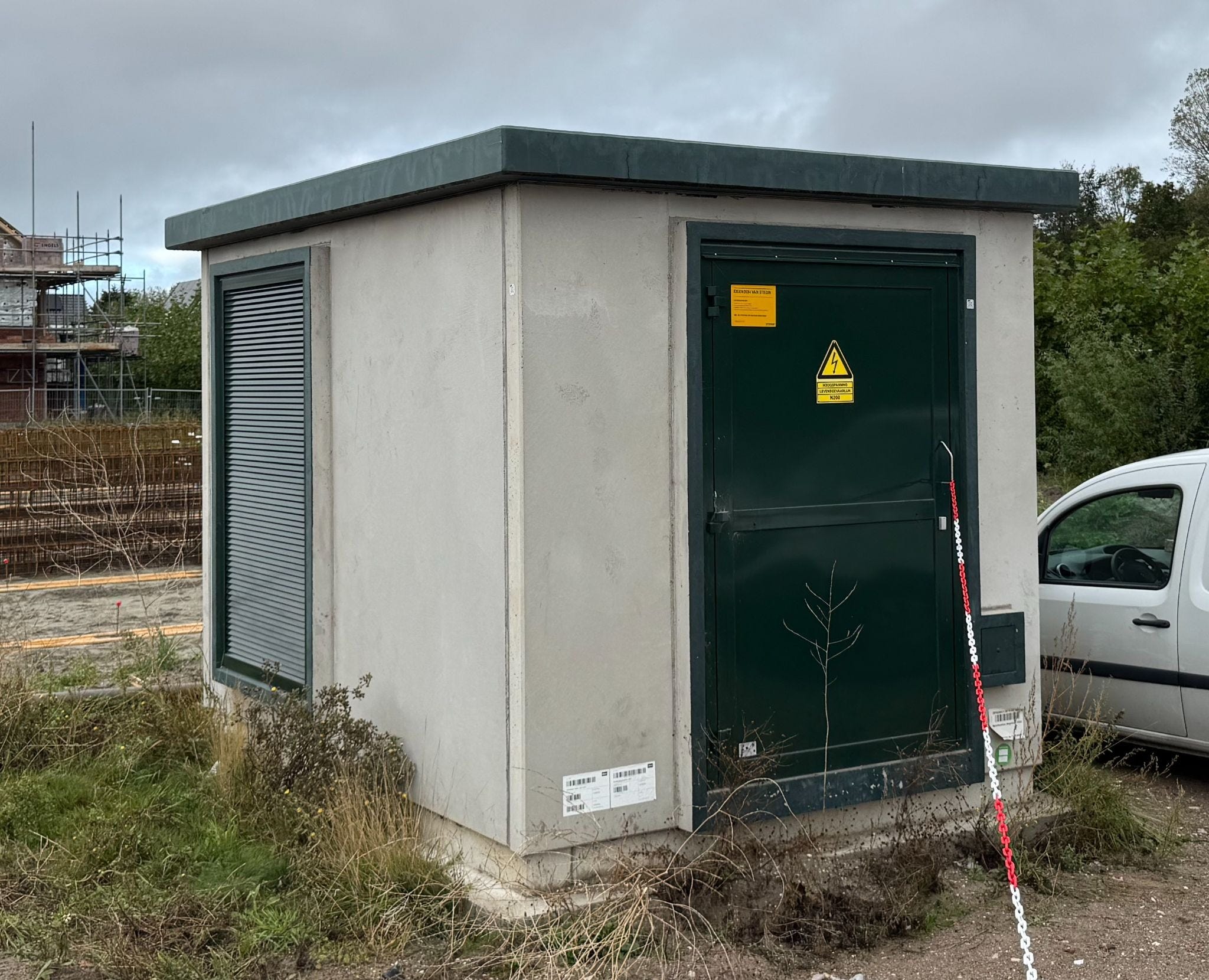
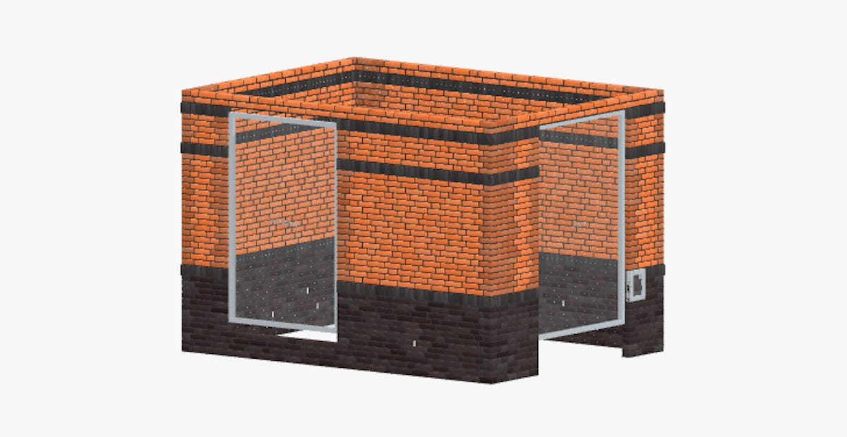
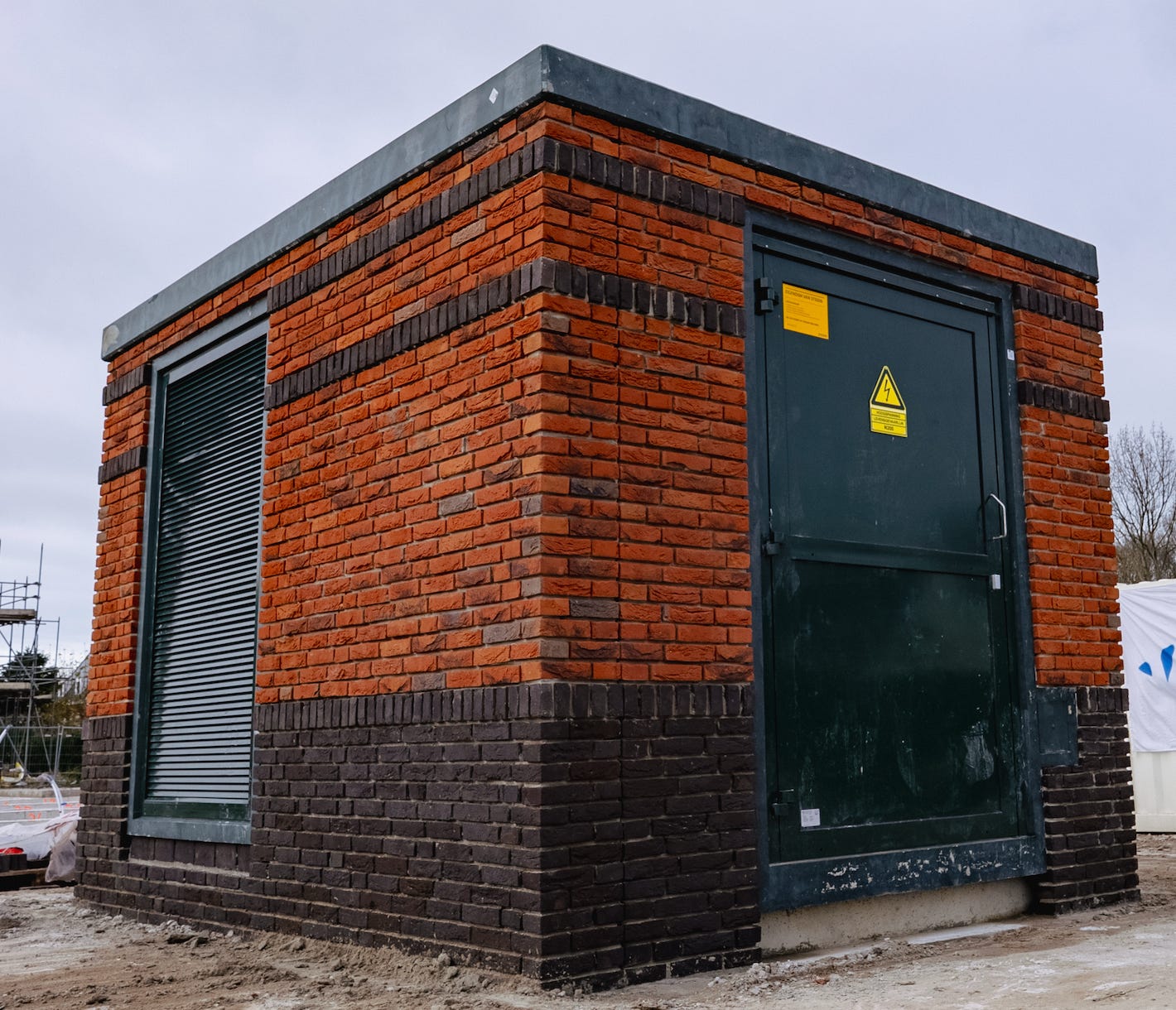
In fall 2025, Monumental was contracted to build a small, unassuming transformer box near The Hague in the Netherlands. After reviewing the drawings from the contractor, we realized we hadn’t built a wall with the required bond patterns before. We traditionally had built various types of horizontal bricks but had yet to tackle vertically orientated bricks which are called soldier course bricks. While horizontal bricks look pleasant, being able to build in different orientations allowed us to get to the next level of building for aesthetics.
As a Forward Deployed Robotics Engineer (FDRE), my goal is to ensure that for upcoming deployments (i.e. construction sites), we have the technical capabilities to complete the buildings and if not, either build or work with the various other teams at Monumental to implement the required capabilities. The goal is not to solve the most challenging problems, but to solve the most important problems (although they definitely can be challenging).
From the drawings we received of the transformer box, I wanted to answer a few questions. Can we build this with our current technology? If not, what are the changes and the corresponding timeline needed to build it. Can we productize it and make it robust enough to build a structure and build it well enough? Are we able to deliver a building that we will be proud of that will likely be standing for many decades and viewed daily by the inhabitants of the community we are building it in? Can we get these answers in 1-2 weeks?
Our current wall design tooling did not support modeling and supporting soldier course bricks, which is required to allow the robots to understand where the bricks should go.
The wall design is built with a few main ideas:
First, the wall is modeled as a grid. Each grid corresponds to about ¼ of a brick. Therefore we figure out the height of the wall, the width of the wall, and break up the dimensions into grids. We set the ideal spacing horizontally and vertically between the bricks.
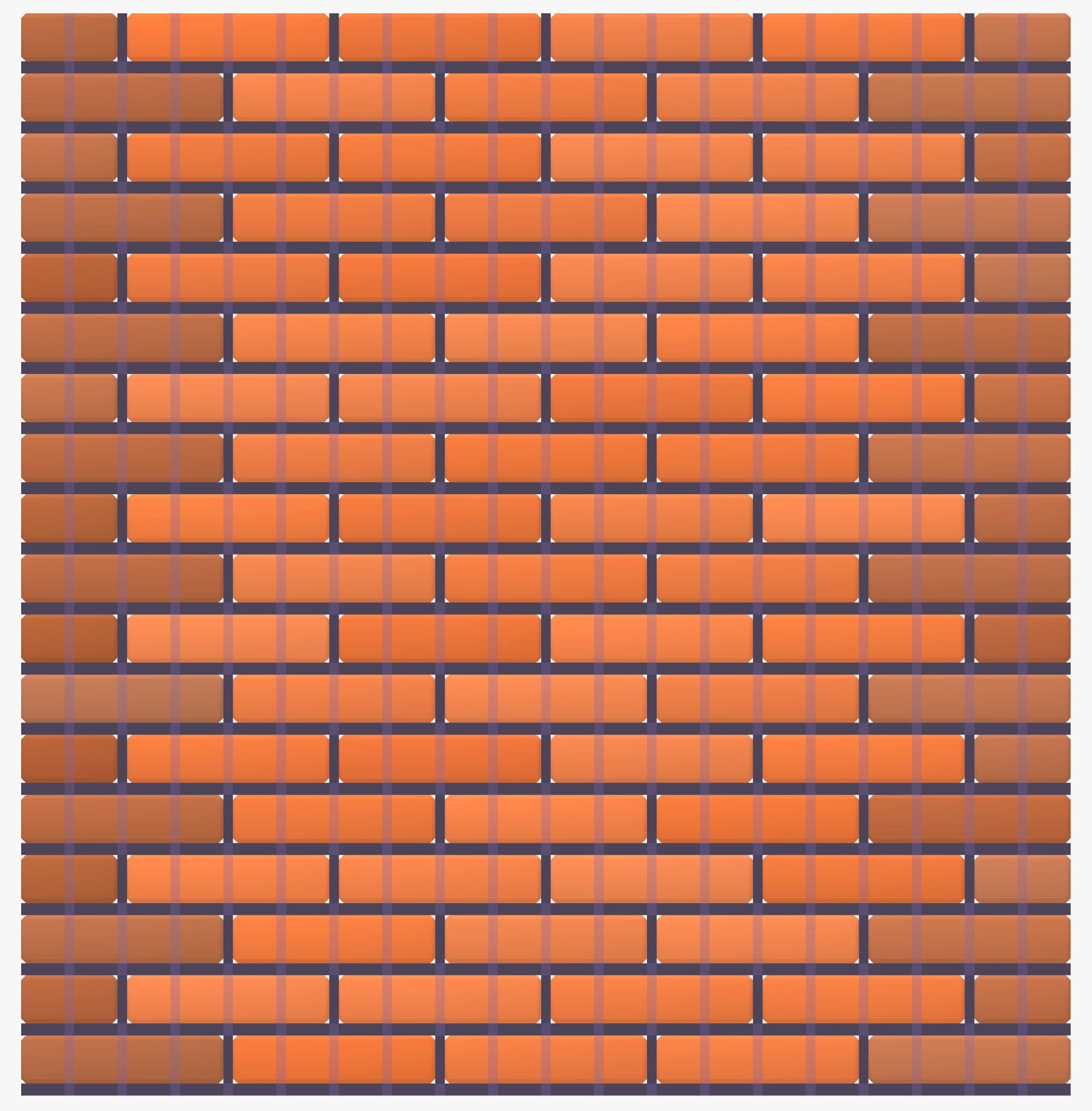
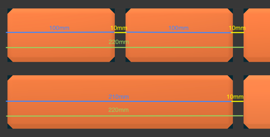
Using standard brick sizes of 210mm length, 100mm width and 50mm height and the standard distance between bricks (head joint) of 10mm:
Horizontal Grid Size: 55mm
Brick length: 210mm
½ brick with head joint: 110mm
¾ brick with head joint: 165mm
Full brick with head joint: 220mm
Why isn’t a ½ brick grid size 210/2 + 10 = 115? Well, remember we want two half bricks to fit in the space of a full brick with a head joint, so we need to make the ½ bricks a little smaller since there is an extra head joint with the two ½ bricks vs 1 full brick. The head joint is the mortar in between the two bricks. The same logic is used for why we break down the grid size to 55mm. This allows us to fill in the grid with 4 grid spaces for a full brick, 3 for a ¾ brick and 2 for a half brick, depending on the required bond pattern.
Vertically, we want to keep equal spacing on the mortar under the brick, which is called a bed joint, so that bricks don’t have larger/smaller bed joints on different parts of the wall. Sounds easy? Unfortunately that isn’t the only constraint. Usually you need to have the top of the bricks line up perfectly with the tops of the windows, sometimes the bottom of the windows, connecting brick segments, etc. This creates an overconstrained problem that requires understanding which constraints to loosen to make the best looking wall. Perhaps you slightly adjust the height of the brick over a long segment, or cut bricks horizontally in a spot that won’t be noticed or maybe you change the spacing underneath certain bricks to catch up to a specific height the bricks need to get to.
The rules are very different. No longer is the height of the brick fixed, instead the width of the brick becomes your limiting factor. For soldier course bricks, now cutting them horizontally reduces the height when they are vertical on the wall.
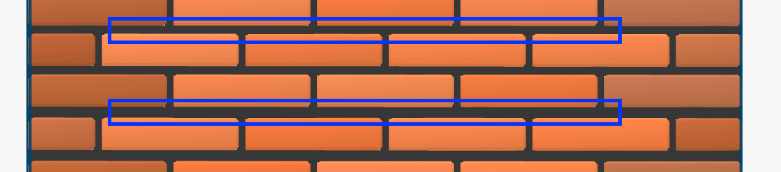
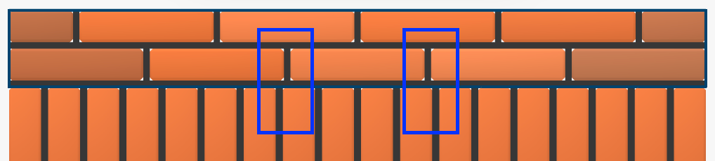
The grid rules still apply, except the bricks extend up instead of to the side. Horizontally, we are now stuck with the length, 50mm, which used to be the height. Cutting bricks in this dimension is too difficult. Therefore, our bricks no longer fit into the grid spacing cleanly since the grid size is 55mm and now our brick is 60mm with a head joint. This effect means that the head joints will not align cleanly (see image below), and we can have misalignment between soldier course bricks and horizontal bricks. Therefore, we may have to adjust the grid size to ensure the spacings and alignment look good enough.
Vertically, the rules can be similar. Soldier course bricks usually can be cut heightwise to the size we want them which gives us more flexibility. If the height is too tall, we can stack regular size bricks and then at the top cut the last brick to the exact size we want.
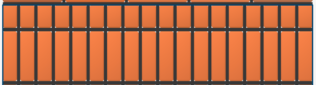
For the transformer, our soldier course bricks were on their own row but we needed to make sure the spacing was appropriate along the sides of the building so the soldier course head joints are as close as possible to the spacing between the bricks for the horizontal bricks.
Now, with the problem of modeling the bricks finalized, we had the building properly modeled in our application to load onto the robot to begin construction.
Brick laying is all about millimeters. A few millimeters off in certain directions can be noticeable and cause degraded aesthetics. How do humans do it? With lots of guides and references. How do our robots do it? A very sophisticated chain of components, including vision systems, kinematic chains, and real world and robot world alignments. All of these sub components need to have sub millimeter accuracy to enable a final error that is within a few millimeters.
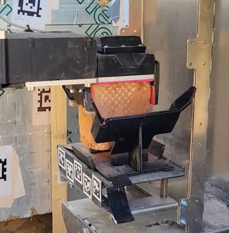
One particular component of this chain is figuring out where the brick is in the gripper which we call pick quality (i.e. how well did the robot pick up the brick). Even if every other component is perfect, if the robot picks up the brick slightly off-center, we need to account for this offset, otherwise the brick will be placed incorrectly in the wall. Below is a picture of a standard pick quality where we figure out exactly where the brick is with respect to the camera. This gives us a x,y,z and roll/pitch/yaw offset that we can account for when placing the brick into the wall.
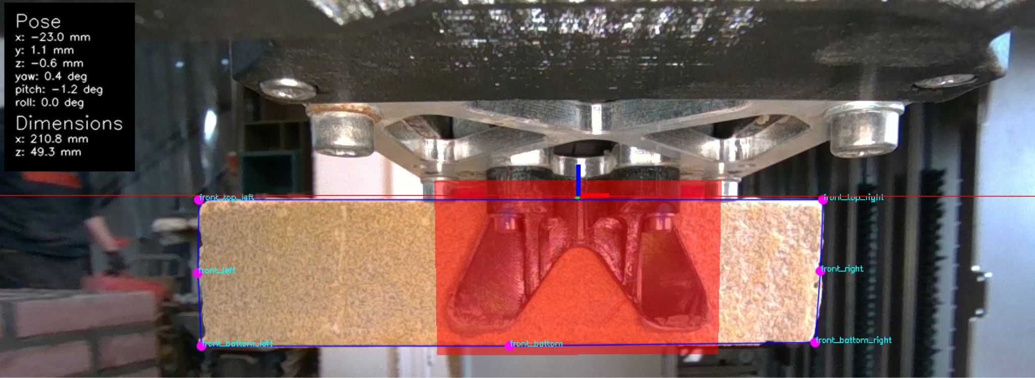
To solve this problem we use a neural net that is trained to detect the corners of the brick. Since bricks vary in size, shape, and straightness, we generally judge the shape of the brick via the top corners and the edge position of the brick. We train our model to find these points on many bricks from various conditions, backgrounds, brick sizes, and colors. This gives us a relatively robust model.
How does this play into our vertically oriented bricks?
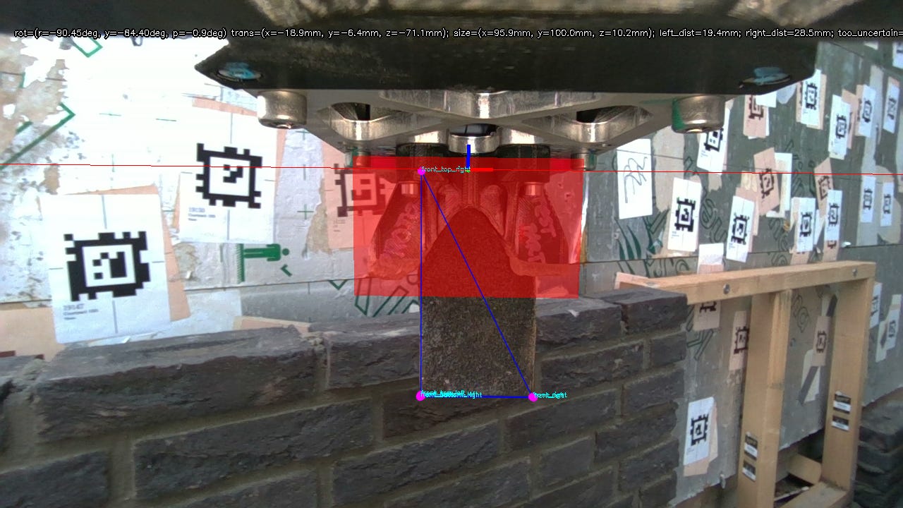
Unfortunately, we had trained exclusively on horizontally oriented bricks so the model broke down on the unexpected input. Therefore we had work to do. Given our short timeline, I worked with the vision team to construct a timeline of potential solutions balancing complexity, time duration, and optimal solution. Plan A was to retrain the model to support vertical bricks, although this may require a lot of work and we may not get enough samples to have a robust model in time. Plan B was to create a new algorithm using more assumptions to unblock us for now.
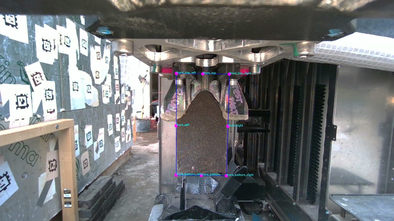
For Plan B, we used the assumption that we know the brick is vertically placed in the gripper. From there, we also made an assumption on the general size of the brick. Therefore, we created a general assumption of where the brick is and the size it should take up. For the gripper vision system, we had stereo cameras computing depth at every pixel which we used to figure out where the brick is. For the first iteration, we assumed the brick is perfectly vertical in the gripper and flush against the back of the gripper which allows us to lock the y and z dimensions of the brick and additionally this lets us lock the roll, pitch, and yaw. This left us with the most critical dimension of x. To find x, we took our size assumption and slid the assumed brick position along the depth results and scored which box has the most expected depth positions within that box. The one with the best match is where the brick actually is in the gripper. This then provided our millimeter level x offset which we can then account for when placing the brick into the building.
For our deployment in The Hague , we proceeded with Plan B since it provided a simple and robust enough solution for our first attempt at vertical bricks.
Our robots work as a trio. One to lay the bricks and mortar, one to supply the bricks, and one to supply the mortar. Up until this point, we only have laid horizontal bricks so how can we adapt our systems to supply and pick up vertical bricks?
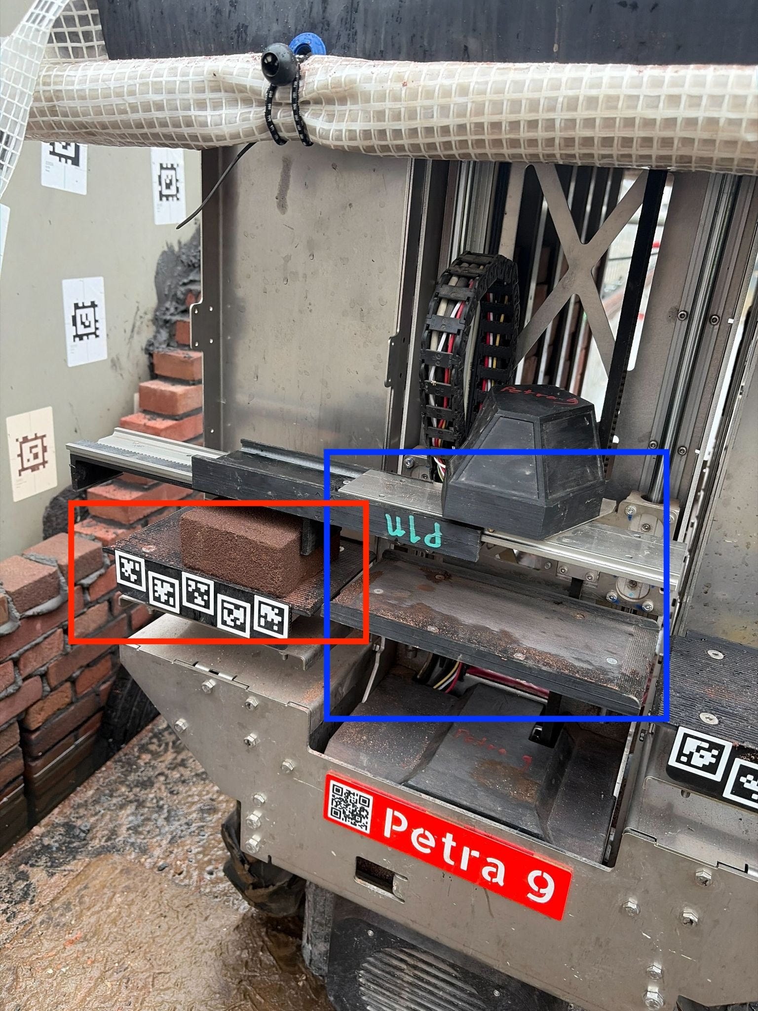
First, how does the current system dispense horizontal bricks? First the carrier, in the blue square, grabs a brick from within the system. The carrier has two main components. It has a lift so it can go up and down and then a puller which you see extended to the left of the carrier, which is used to pull and push bricks. When a specific brick is needed, the carrier brings the brick to the platter, in the red square, and will push the brick onto the platter using the puller, as shown below. From there, the brick laying robot can grab the brick off the platter.
Problem for soldier course bricks? The brick supply system is fixed in rotation and thus couldn’t rotate the bricks vertically and the gripper on the brick layer robot also can’t rotate to place the brick in the wall. Hmm time to iterate and think creatively.
The goal was to come up with a solution in 1-2 weeks time that we could reliably rotate the bricks, productionize, and retrofit our systems quickly to get us ready for our deployment coming in a few weeks.
I sat down and thought over many possibilities. We could add a rotation axis to our brick layer which would be the ideal solution but that would require significant hardware development, recalibration, and retrofitting. We could add a rotation to one of the brick supplier robots components to rotate the brick before putting it onto the platter but similarly that would require developing an actuator and new rotatable hardware components.
Given the timeframe, a passive system was needed. The two degrees of freedom on the brick supply is the Petra lift and puller. The lift moves the brick up and down and the puller pulls and pushes the brick to the side.
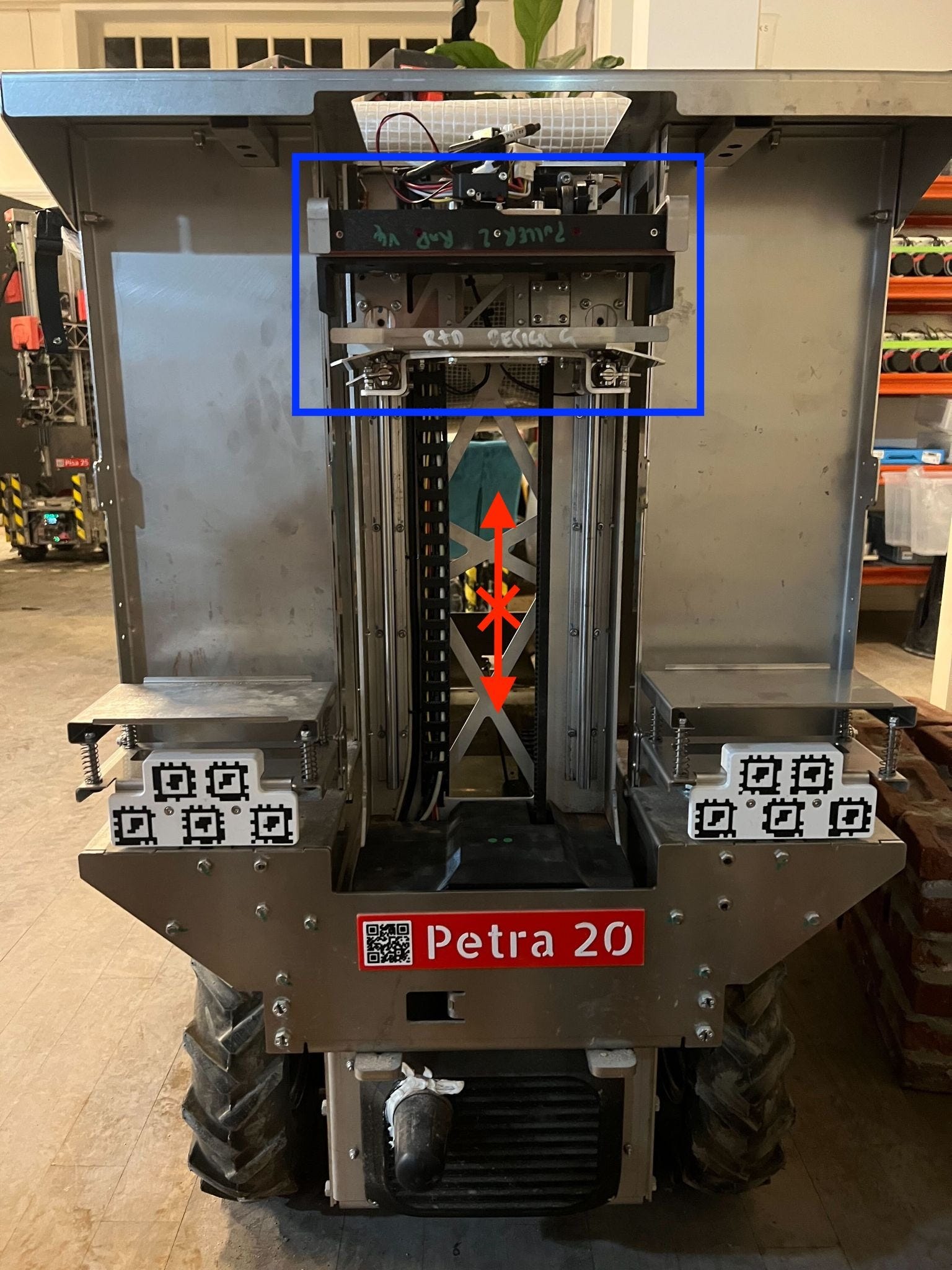
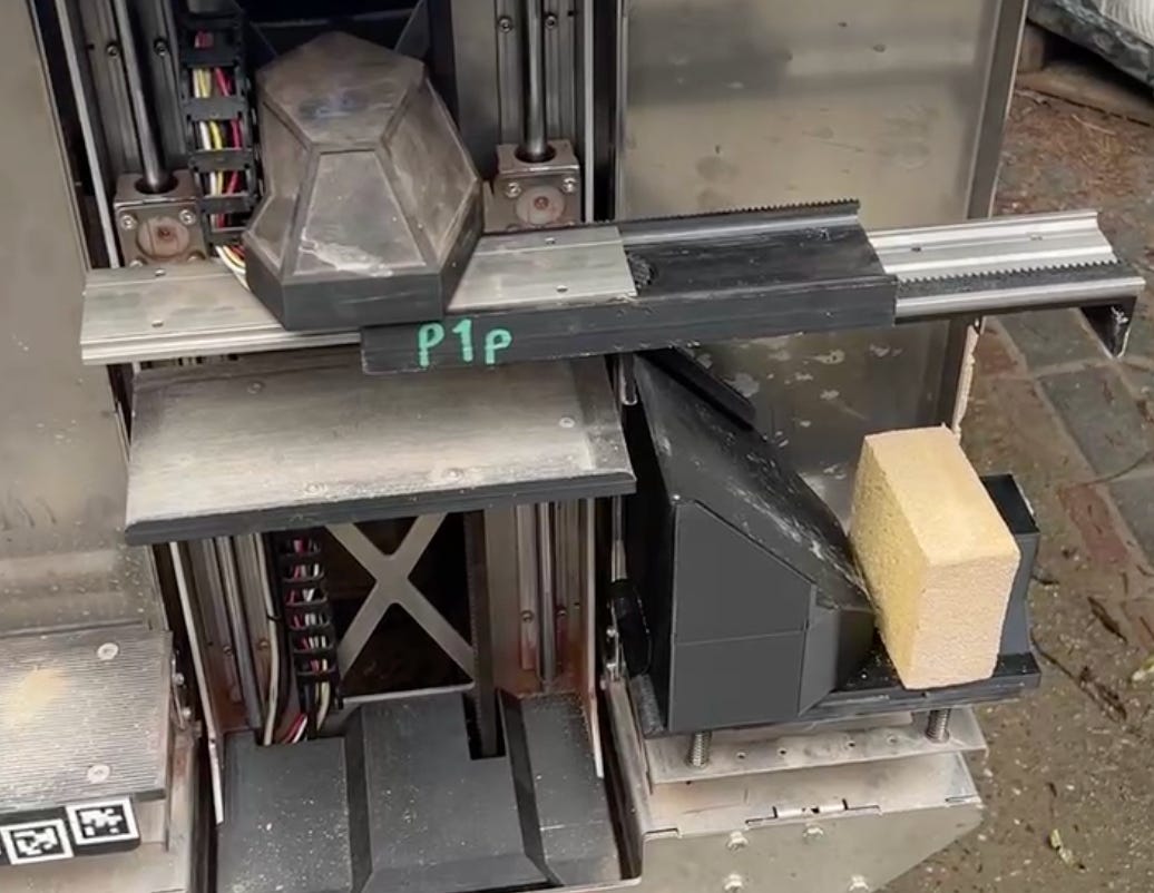
If the Petra lift is brought high, and the puller pulls the brick off the carrier, the brick itself will generally upright itself as it comes tumbling down. If the fall can be controlled, the brick could potentially rest reliably on its short side to orient it vertically. Working with a colleague on the hardware team, we got to prototyping this by quickly 3D printing and iterating the “Petra slide”. The first few prototypes had about a 50% reliability of positioning the brick reliably vertically. The other 50% the brick had too much momentum and toppled over, or it got stuck and didn’t tilt far enough. In certain cases, the Petra slide got in the way of the carrier and snapped. This approach showed promise but needed to be tuned to have the right angle, the right approach, and the correct pull speed so that the brick stayed vertically and also didn’t twist too much.
In the end, after multiple iterations of testing, a metal version was made. This was iterated on a few times as well and finally a version was made in time for the deployment and allowed us to successfully rotate the bricks to supply the bricks to the brick laying robot.
Well, can robots make pretty things? Here at Monumental we are now marching in this direction. Vertical bricks were the challenge for this power transformer in The Hague but what will be next? Curved walls, arches, angled bricks? We want to enable building all of these features without extra costs.
Monumental aims to decrease the cost of construction but also not at the cost of aesthetics. This will enable us to alleviate housing shortages in the Netherlands, and ultimately more countries around the world. We are running deployments in the UK this year!
While building these systems requires a team of extremely talented individuals at Monumental, as a FDRE, I help build and push the developments to practical needs. If you enjoy figuring out which problems are critical, creatively solving challenging problems, and have a strong understanding of the big picture of the product, then you should join as a FDRE at Monumental!