Prologue
I recently moved in a new apartment in which the living room lights could be controlled with a remote. Having already played with IR signals in order to incorporate remote control to some of my projects I knew that I would probably be able to emulate the signals sent by the original remote and thus operate the lights of my living room from a web based application.

My first reflex was to think of using an Arduino with a wifi/ethernet shield. I could have used the ever usefull aRest library in order to build a REST api on the microcontroller. The web-app would have been hosted on a remote server and used as an graphical interface in order to make the right calls to the Arduino.
But this time I wanted to take a less low-level approach and it was a perfect opportunity to get my hands on a raspberry pi. With its computing and networking capabilities plus a direct control over the GPIO pins, the pi allows me to run the web-server and manage the IR signals from the same device. Furthermore I can use packages that will make my life so much easier, and use the full potential of the Pi to create a very complete hub for my domotics needs.
What we will be making
The idea is to make a web application that will allow us to easily control our home appliances. The project is based around the Raspberry pi which is used to :
- Record and store the IR signal of the remotes we wish to emulate.
- Play back the signals in memory.
- Host a web-app working as an interface with the IR module.
Additionally, we’ll see how we can leverage the capabilities of the pi in order to add more functionalities to our application.
The whole project relies on the Open Source Universal Remote created by Alex Bain.
Table of contents
- Part 1 : Handling IR signals : Hardware.
- Part 2 : Handling IR signals : Software.
- Part 3 : Setting up a web-application with NodeJs.
- Part 4 : Additional functionalities.
Handling the IR signals : Hardware
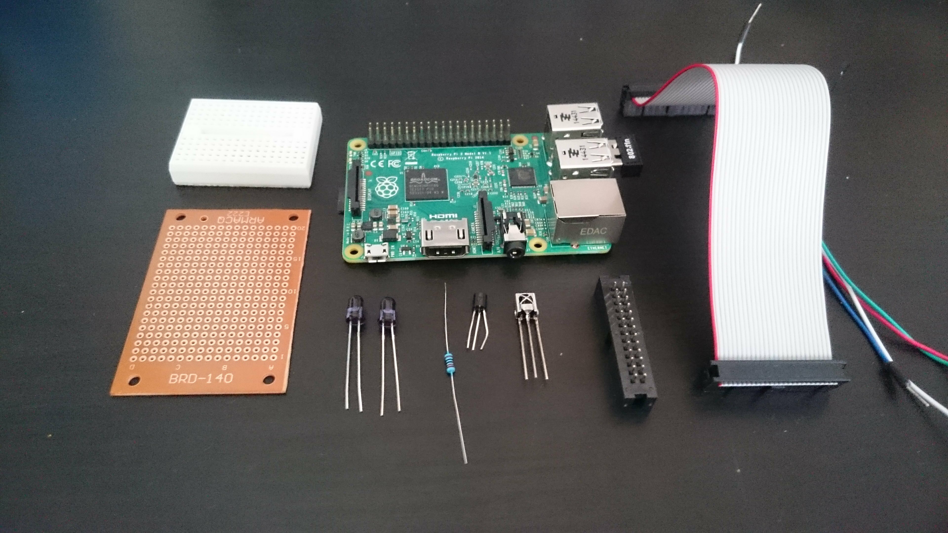
Components list
- 1x Raspberry Pi
- 2x 940 nm IR LEDs
- 1x P2N2222 transistor
- 1x 22 ohms resistor
- 1x 10k ohms resistor
- 1x TSOP38238 38KHz IR receiver
- 5x female to male jumper wires – for breadboard circuit
- 1x breadboard
- 1x protoboard
- 1x box header
- 1x GPIO Ribbon cable
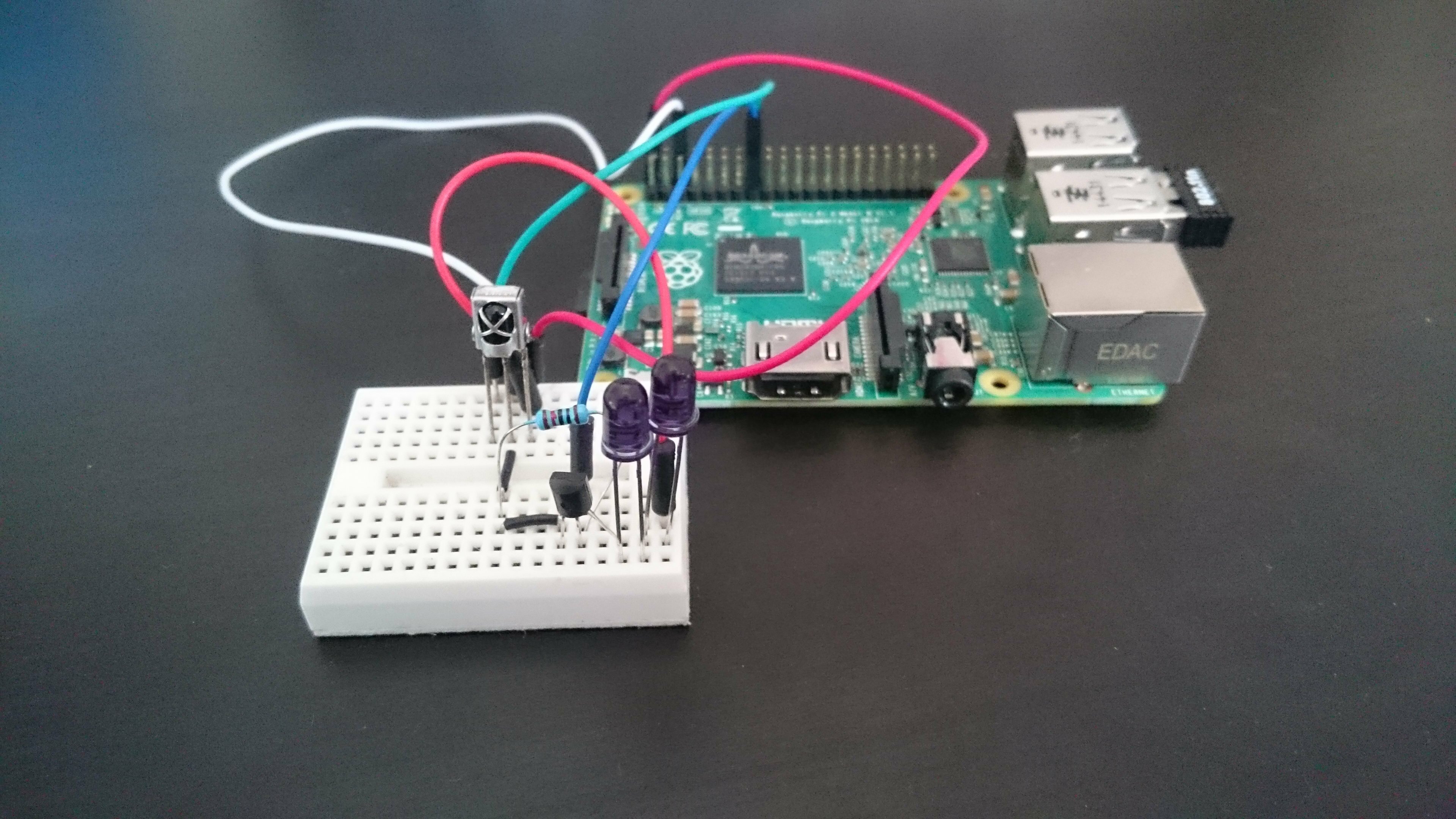
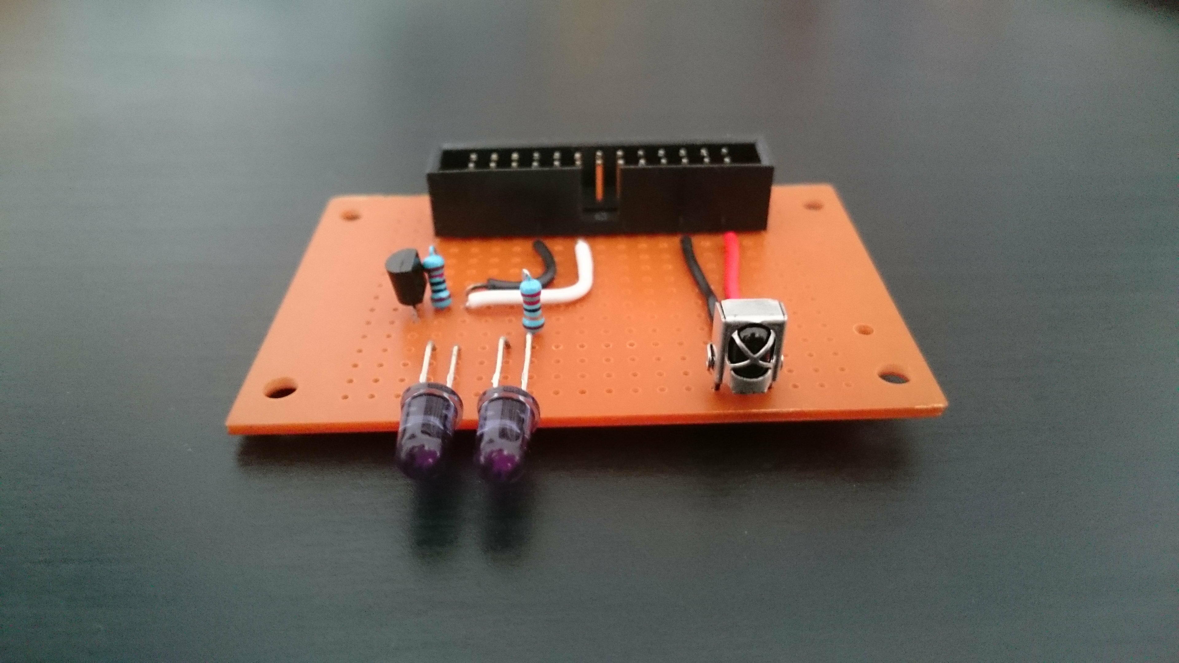
Note 1 : You might notice that a resistor is missing from this picture and the next depicting the circuit on breadboard. It’s because I included it later on after I received additional advice on the circuit. So the missing resistor should be there. In case of doubt, trust the schematic, not the pictures.
Note 2 : choose the GPIO ribbon cable and the header according to your version of the Pi. Version 1 uses 2×13 pins, version 2 uses 2×20. Or you can use a 2×13 on a rsp2 like I did so that some gpio pins stay accessible directly on the pi, but you might have to modify the header of the cable a little bit (scratch a bit of plastic on the side so that it can plug in correctly).
Making the circuit
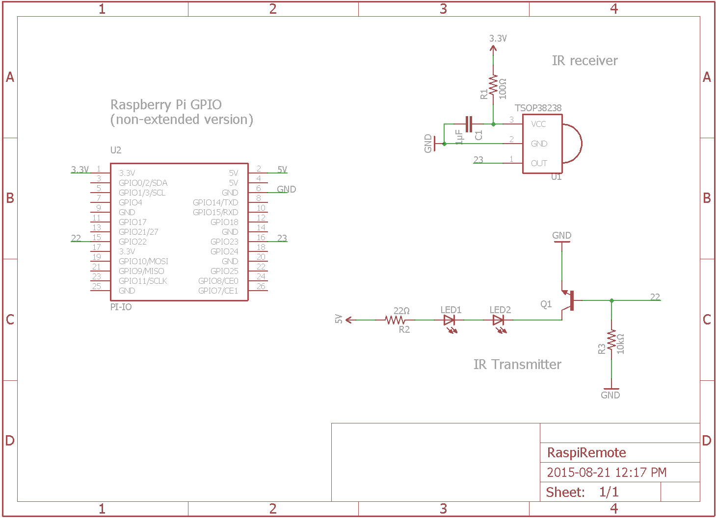
We are going to start by testing everything on a breadboard to make sure that the components work properly. It is a rather simple circuit : the IR sensor is powered up by the 3.3v pin and the output goes to one of the GPIO pins. A NPN transistor controlled by another GPIO pin is used to switch the LEDs on and off. We can’t connect the LEDs directly to one of the GPIO pins because the current provided wouldn’t be enough. Finally two resistors are used, one to limit the current coming in to the base of the transistor and the other to protect the LEDs.
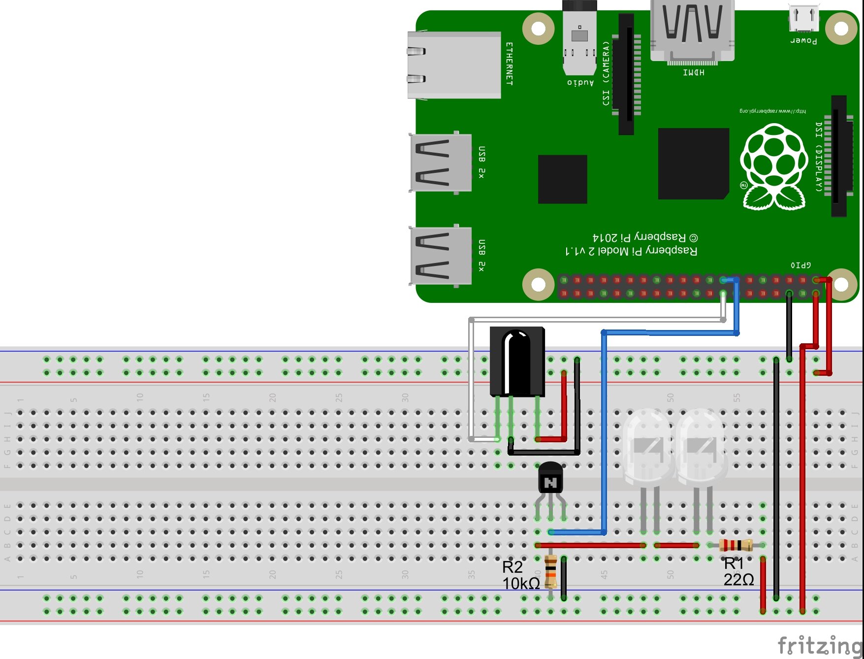
Note : how can you find the proper value for the resistor R1 ? Using Ohm’s law of course ! The formula is R=V/I. Here V is the total voltage available minus the consumption of the two LEDs and the transistor. These informations can be found on the datasheets of your components. For the transistor, look for the voltage drop which is indicated by the collector-emitter saturation voltage VCE(sat). For the LEDs, you’ll be looking for the forward voltage V(f) and the forward current I(f). The formula thus becomes R = (Vsource – VCE(sat)-V(f)*2)/I(f). Here Vsource = 5, VCE(sat)=0.6, V(f)=1.7 and I(f)=0.01 (100mA). So R=(5-0.6-1.7*2)/0.01 = 100ohms. But since IR LEDs commonly have I(f)=50 instead of 100 we’ll use a 22ohms in order to accommodate a wider range of components.
Now is the time to warm up the soldering iron. In the following schematic you’ll notice two new components R1 and C1. These are optional. The datasheet of the IR receiver advises to include them in order to protect the circuit against electrostatic perturbations. We’re here to learn about good practices aren’t we ? I thus added them to the schematic, but the circuit would work without it. In fact, you’ll see that I didn’t include them myself in the protoboard version but did in the PCB.
I chose to use a GPIO ribbon cable instead of making a stackable version so that the PI and the remote module could be in a somehow different location and orientated appropriately.

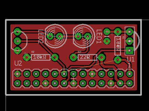
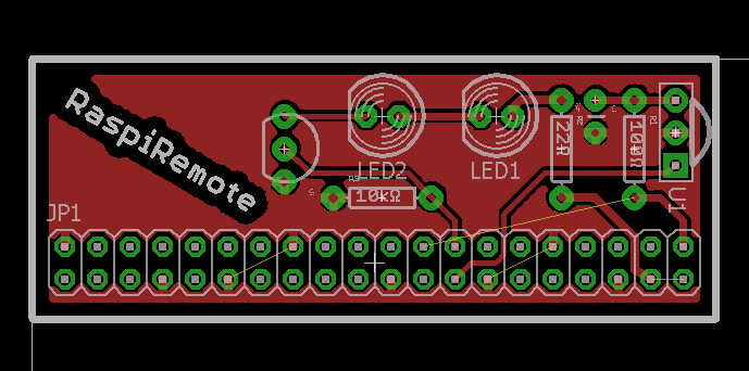
If you are looking for a more “professional” finish, I designed two PCBs using Eagle. One is for the 2×20 gpio version, the other for the 2×13. They can work stacked on the pi or connected via a ribbon cable. Feel free to use them but you should take some time to review them before generating your gerbers and sending them in to production. If you’re wondering about how to do that, I encourage you to check the last tutorial I wrote.
The files for the two versions can be found here.
Handling the IR signals : Software
Preparing the Raspberry Pi
Let’s assume that your Pi was correctly set up and connected to your network, either via ethernet or wifi.
For the package in charge of taking care of our IR needs to work properly, we need to update Raspian OS :
sudo apt-get update
sudo apt-get upgrade
Setting up Lirc
Lirc stands for “Linux Infrared Remote Control”. It is a package that will allow us to decode and to save IR signals for later use. Three of the tools it contains will be most useful to us :
- mode2 : ouputs the pulse/space length of infrared signals to the console
- irrecord : used in order to record IR signals for later usage with lirc.
- irsend : send IR signals from the command line. Signals can be sent once or repeatedly during two calls.
Let’s install it:
sudo apt-get install lirc
We now have to manually configure the driver, setting the gpio pins we will use to receive and transmit the signals.
Edit /etc/modules and add at the end of the file:
lirc_dev
lirc_rpi gpio_in_pin=23 gpio_out_pin=22
The file /etc/modules configures which loadable modules are automatically loaded when the pi starts. More info here.
Add this at the end of the file holding your system configuration parameters /boot/config.txt:
dtoverlay=lirc-rpi,gpio_in_pin=23,gpio_out_pin=22
Next edit lirc hardware’s configuration file /etc/lirc/hardware.conf with the following details:
########################################################
# /etc/lirc/hardware.conf
#
# Arguments which will be used when launching lircd
LIRCD_ARGS="--uinput"

# Don't start lircmd even if there seems to be a good config file
# START_LIRCMD=false

# Don't start irexec, even if a good config file seems to exist.
# START_IREXEC=false

# Try to load appropriate kernel modules
LOAD_MODULES=true

# Run "lircd --driver=help" for a list of supported drivers.
DRIVER="default"
# usually /dev/lirc0 is the correct setting for systems using udev
DEVICE="/dev/lirc0"
MODULES="lirc_rpi"

# Default configuration files for your hardware if any
LIRCD_CONF=""
LIRCMD_CONF=""
########################################################
Reboot your Rasbperry Pi. You should be all set. We are ready to try out our system.
Registering new IR signals
We are going to make sure that our circuit and lirc are working properly by using mode2 to output the characteristics of an IR signal. Start by stopping lirc and launching mode2.
sudo /etc/init.d/lirc stop
mode2 -d /dev/lirc0
Your pi is now listening to IR inputs. Point a remote to the receiver and press any button. The program should output something similar to this, indicating that the reception side of things is all set.
space 14529891
pulse 8451
space 4734
pulse 274
space 884
pulse 403
space 532
pulse 635
space 649
pulse 440
space 680
pulse 462
The first space is the time elapsed until your pressed the button. The first pulse (8451) is the start pulse, used to notify the receiving device that information is coming. Here are some additional informations on how IR signals work.
Now to properly record the signals. We will use irrecord in order to do so. It will record the signals from the remote(s) control and create a .conf file for lirc.
Note that a repository exists where .conf files have been made available for the most common remotes.
We will anyhow create our own. To generate a remote configuration file, first stop lirc so that /dev/lirc0 is available for irrecord to use.
sudo /etc/init.d/lirc/stop
To register a new remote control, you’ll need to press each button of the remote several times (it should be less than 10) until two rows of spots have been filled. You’ll be asked to enter a name for each signal, which will be stored as an hexadecimal code. The output is saved in ~/lircd.conf.
irrecord -d /dev/lirc0 ~/lircd.conf
Sometimes irrecord doesn’t quite get the signal and prints the dreaded message : “Can’t find gap”. Hopefully we can circumvent this problem.
Using the -f option on irrecord will force the raw mode which will create a raw (read plain non-hexadecimal) codes configuration file. You can then try your luck with -a which will analyze the file just created in order to get clean hex codes from it.
irrecord -f -d /dev/lirc0 ~/lirc.conf
irrecord -a ~/lirc.conf
If everything else fails, you can still output mode2’s code in a .conf file.
mode2 -m -d /dev/lirc0 > ~/lirc.conf
Next edit ~/lirc.conf, delete the first value so that the first is the start value we discussed earlier. Complete the file with the following lines:
begin remote

   name  REMOTE_NAME
   flags RAW_CODES
   eps            30
   aeps          100
   frequency    38000

       begin raw_codes

           name COMMAND_1
--- RAW CODE FOR COMMAND_1 ---
           name COMMAND_2
--- RAW CODE FOR COMMAND_1 ---

    end raw_codes
end remote
You can try other frequencies depending on your remote. Note that the indent should be made of spaces not tabs.
When you’re done with that part, make a backup of the original lircd.conf file, copy the new configuration file and restart lirc so that we can send a signal back.
sudo mv /etc/lirc/lircd.conf /etc/lirc/lircd_original.conf
sudo cp ~/lircd.conf /etc/lircd.conf

sudo /etc/init.d/lirc start
Playing it back
Using irsend is pretty straightforward. It can send a signal once by using irsend SEND_ONCE REMOTE_NAME CONTROL_CODE or repeatedly between two SEND_START and SEND_STOP calls. LIST can help by giving you a reminder about the codes available on a remote.
irsend LIST REMOTE_NAME ""
irsend SEND_ONCE REMOTE_NAME CONTROL_1
Is it that simple ? Yes it is. But we don’t want to be restricted to the shell to control our hub, do we ? So let’s continue to the next part.
Setting up a web-application
Remember Alex from earlier ? Well he gave us an open source NodeJs client called lirc_node to interface with lirc. Not happy yet ? Have I mentioned that he also wrote lirc_web, a sample application for lirc_node which I forked in order to adapt it to my specific needs.
Setting up NodeJs
This is going to be quick. Simply download the latest package optimized for ARM (the kind of chip that runs on your pi) and install it!
wget http://node-arm.herokuapp.com/node_latest_armhf.deb
sudo dpkg -i node_latest_armhf.deb
To test your installation type node -v which should output v0.12.7.
Setting up lirc_web
To state the readme :
lirc_web is a nodejs app that creates a web interface & JSON API for the LIRC project. It uses lirc_node to handle communication between LIRC and nodejs.
This project allows you to control LIRC from any web browser – phone, tablet, or desktop. The mobile web interface is responsive and optimized for all sized displays. In addition, with the JSON API, you can control LIRC from any web connected device – pebble watch, myo armband, emotiv EEG headset, or beyond.
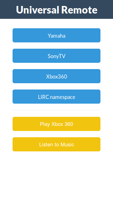
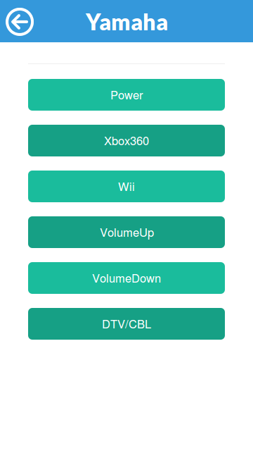
It’s really some great work from Alex. The basic interface uses lirc’s configuration file to list all the remotes and provide a simple but neat interface in order to use the commands registered from the web.
Installing it is as easy as 1 2 3. Navigate to the folder containing your node web apps :
sudo git clone https://github.com/alexbain/lirc_web.git
sudo npm install
node app.js
Et voilà ! The website is now online. To access it, find your local ip with the ifconfig command in the “inet addr” field. The address will be something like http://192.168.2.xx:3000.
If you want the server to get online automatically when the pi boots up, I encourage you to read a great tutorial by -yet again- Alex since I would only be paraphrasing him otherwise : running lirc_web with Nginx and Upstart.
Accessing the App from outside the network : port forwarding
At that point you may have tried to access the website using your cellular-network-connected smartphone and noticed that, damn, it doesn’t work! (I know I did and it took me a minute or two to realize why). So why is that ? Well the ip you got earlier is only worth something inside your network. Between that and the outside world stands your router. If you want an external request to reach your pi you have to set up what is called port forwarding. It means that when your router receives a request on a pre-defined port (a request made on the your public ip visible to the outside world, contrary to the local ip), we want it to redirect (forward) the request inside the network to our pi.
Usually the control interface of routers is accessible at this address : http://192.168.2.1/. Check your manufacturer’s documentation if not. In my case things look like that :
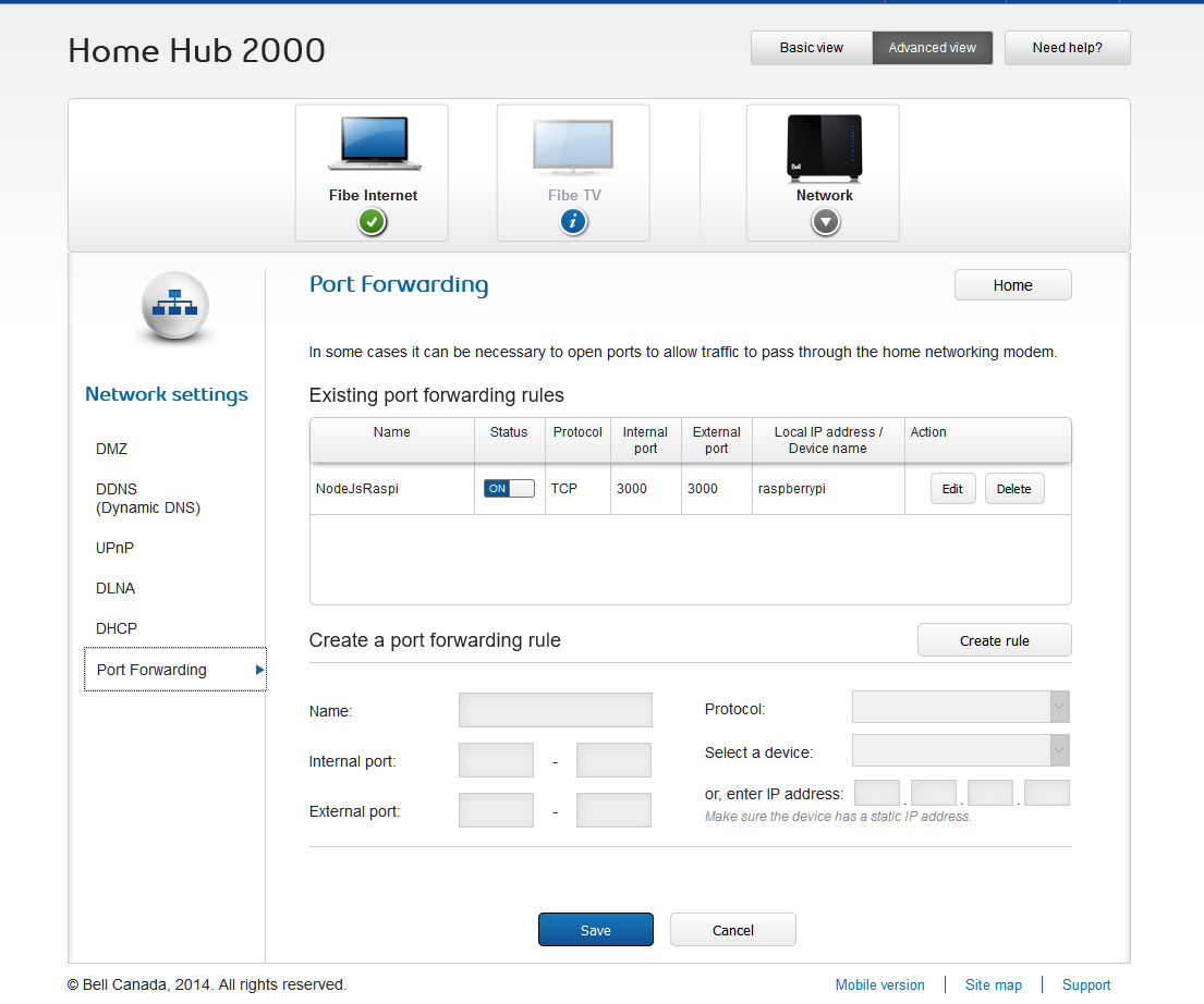
To set it up, create a new rule where the external port is the port from which the request is coming, the internal port is the one inside your network where the request should be redirected to and the local device is, you guessed it, your raspberry pi. If your router doesn’t offer the option to target the device by name you might want to think about setting up a static ip on your pi otherwise the rule will be broken if the pi gets assigned a different address by the router.
You can now access your website from the outside world, yay ! To find your public ip, just google public ip 😉
Additional functionalities
Now that you have the foundation of the system up and running, it’s time to open your favorite text editor and start tweaking things up ! lirc_web provides an awesome starting point for that since it creates an api that makes it very easy to interface with lirc from a web app.
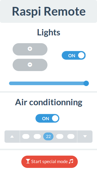
I made my own version of the interface in order to match my needs. It includes control for the AC and the lights, and I added a little button just for fun. You see I’m a big fan of Glenn Quagmire from Family Guy (giggity) and I always envied his ability to turn his house to a love nest at the press of a button. So I made a “special button” that, when pressed, turns on the lights and lowers them to a “comfortable” level, turns on the AC to an “appropriate” temperature and plays this very cheesy music. I used mpg123 in order to be able to start a music player from the command line and subprocess in order to send a command to the bash from the node application.
The forked repository is here if you want to have a look.
Thanks a lot for taking the time to read me. I hope that this guide will be as useful as can be. Don’t hesitate to drop a comment if you spot a mistake or if you have any question!