Homemade 6 GHz pulse compression radar
hforsten.comI remember this article from the same site a while back - https://hforsten.com/heartbeat-detection-with-radar.html
I bought some cheap 10ghz and 24ghz dopper radar units off of amazon and started tinkering with them. You can absolutely pick up heartbeats and breathing just visually in the spectrogram.
Here's a few samples from that era:
10ghz pointed at ceiling fan:
https://www.youtube.com/watch?v=tIiFvByf1CQ
10ghz pointed straight up underneath a quarter that I flipped and allowed to land on the surface
https://www.youtube.com/watch?v=8riretP8ylE
10ghz pointed at a quarter spin on the surface
https://www.youtube.com/watch?v=5lnYvJoxRak
The comb filtering of the signal from the spinning surface is really cool.
10ghz module on amazon - https://www.amazon.com/HiLetgo-Microwave-Detector-Wireless-1...
interesting does/can it work behind structures? is it safe to point this at yourself?
yes, it's safe. It's not that different from regular WiFi or cellular signals.
It's non ionizing (aka it doesn't have enough energy to instantly destroy cells unlike uv radiation) but it can heat up tissue, which is linked to cancer and worse (think microwave ovens).
There’s no risk of cancer from heating up tissue.
I did some reading and it seems you are right.
No Idea why phones come with a SAR rating then and why there are safe limits defined, when no one found unsafe limits.
Tiny amounts of cell heating/cooling have been found to change the cell differentiation mechanism. That's the reason ultrasound energies are limited during pregnancy and it's recommended not to do too many ultrasounds.
I don't see why microwave heating wouldn't cause the same effect.
Because you tend to hold phones right to your brain.
Personally, I perceived it as a matter of good engineering: your phone shouldn't spend its energy to heat your ear.
Interesting! There might be other unintended issues from transmitting heat, I suppose?
Even from transmitting heat to the phone's components itself or other items that are nearby, e.g. laptops: https://www.ncbi.nlm.nih.gov/pmc/articles/PMC5219578/.
Afaik the transmission energy of a cell phone is limited to a maximum of 1 or 2 Watts (depending on which frequency it operates on). This power is a maximum that will only be used if the reception is bad.
In the wavie scene (people who are paranoid about radio waves controlling them) shielding those devices is a typical approach — this is also where the meme of the tinfoil hat comes from. Ironically that shielding makes your cellphone operate with the maximum transmission power at all times.
There is but it's sun burn type risks, not nuclear reactor type.
A few unlucky people have been literally cooked to death by military radar. It's as awful as it sounds.
Isn't sun burn damage and nuclear reactor damgage the same type but at different magnitudes? If your skin becomes red and hot a few hours after being exposed to the sun it's because your immune system is killing off cells that had their DNA damaged. The damage is not caused by heat but by radiation.
https://www.thenakedscientists.com/articles/questions/why-do...
> It's as awful as it sounds.
Well to me it sounds like you'd get heat stroke and pass out before anything reaches particularly painful temperatures, because it's heating you pretty evenly and not via contact, but maybe that's not the right way to think about it?
At higher frequencies I would guess it gets closer to normal burning?
This isn't really correct I'm afraid. The cause of SAR is predominantly dielectric losses and the loss tangent is a strong function of tissue type -- CSF, fat and bone are really quite different in terms of epsilon r and sigma, and one has to solve Maxwell with a human voxel model to work out SAR effectively which computationally is a pain.
Once tissue heating has occurred what happens next is well described by the bioheat equation, which is basically the thermal diffusion equation with a massive percussion term. The blood supply is very different to different tissue types and the depth at which peak heating occurs is a very strong function of wavelength.
For frequencies, the combination of these effects means that your eyes are most at risk -- water like and terrible blood supply. This gives rise to the first piece of advice I was given when a graduate student playing with electron paramagnetic resonance -- never look down a waveguide and treat them like a loaded gun!
Perfusion not percussion! Damn autocorrect...
> because it's heating you pretty evenly and not via contact
My microwave oven disagrees
Without knowing anything about tissue interactions the reason why microwaves heat so unevenly is the sanding pattern that waves make.
If you want to get heated evenly, don't remove the spinning glass plate before entering your microwave oven.
But there is a risk of dying from heating up tissue.
I have a "human presense sensor" which is a 5GHz radar. It works behind structures, detection is weird sometimes but much better than a passive infrared sensor for this use case.
This is great.
It’s the last piece I needed for my suburban missile guidance system! This will be the last year the Joneses survive the annual block party.
Can you do phased array radars next? I need the extra precision. There’s a few neighbors who don’t clean up after their dogs…
There is this:
https://www.crowdsupply.com/krakenrf/krakensdr
(Although they had to take the radar elements out of the firmware/software, most likely due to ITAR - ref link: https://forum.krakenrf.com/t/where-has-the-passive-radar-cod... )
A similar ITAR restriction on controlled reception pattern antennas means that GPS jamming is still much more of a problem than it needs to be. Three antenna elements are all you get, according to this: https://www.gpsworld.com/toughen-gps-to-resist-jamming-and-s...
Interesting article. I wonder if any progress on the ITAR issue has been made since 2022? If Brad Parkinson can't steer ITAR in the direction of common sense, nobody can. (For those who don't know, he was the principal architect of the original Navstar GPS system.)
Nothing can steer ITAR into the direction of sense.
I’ve had to go to extremely ridiculous lengths to buy downlead cables for a headset recently because the cable was deemed ITAR.
I would prefer we not have homemade cruise missiles all over the place. The people who need them can make them after all.
Apparently the hobby drone racers are doing that now: https://www.abc.net.au/news/science/2024-04-05/how-a-small-c...
And it's certainly not just a recent Ukraine related thing either: https://www.nzherald.co.nz/nz/boffin-builds-backyard-missile...
Sure, it's getting increasingly easier to just buy China made for ITAR-protected products. Night vision cameras, thermals, drones. They're fine, way more user friendly, often cheaper too.
There are now even Gen3 night vision tubes being made in China.
They aren’t quite as good as US made ones yet, but it’s getting pretty close.
To be fair, nobody actually neeeds cruise missles
I need some, for mail delivery. Those messages won't send themselves.
When it comes to getting the message across, never underestimate the bandwidth of a W84-equipped GLCM.
Congratulations, you are why we can't have nice things.
Wow. I haven't looked at the ITAR list in decades. There are lots of electronics items on there now that have useful civilian applications and can be built at low cost. You can build such things, but can't ship them cross-border to or from an ITAR country.
I'm amazed at what people are building as hobbyist RF gear. I wonder what test equipment they have. The test equipment for GHz RF is very expensive. If you build it and it's not working, you may need test gear.
(I tried to build a LIDAR in 1990s. It didn't work, and I didn't have access to gear that would let me see what was happening up there.)
Thank you for the link!
I totally forgot about kraken. I cloned their repo in November 2022, probably in anticipation of the ITAR hiccup. Hopefully the radar code is there.
I’d be interested in knowing if you’ve got that. I was going to buy one but the pull of the code put that on ice. I may pull the trigger if I can get the code!
If you are a foreigner, you're asking the OP to commit a federal crime.
If you're an American national, you're likely asking the OP to commit s federal crime.
ITAR's a mother.
No sadly it looks like I got the wrong repo or I cloned it too early. It includes a little Python code but no firmware from what I can tell.
if they really wanted to, they could make this a first amendment case, no?
It would likely end up breaking the first amendment instead.
These should help.
Tactical and Strategic Missile Guidance, Seventh Edition https://www.amazon.com/Tactical-Strategic-Missile-Guidance-S...
Tactical missile warheads https://www.amazon.com/Tactical-Warheads-Progress-Astronauti...
I'm sure the OP has already read his Skolnik given his comment but for those following along that's usually the best place to start.
https://www.amazon.com/Radar-Handbook-Third-Merrill-Skolnik/...
There's also Fundamentals of Astrodynamics https://www.amazon.com/Fundamentals-Astrodynamics-Second-Dov...
Which builds up from first principles a ballistic missile defence system. Always useful to have.
Missile Guidance and Control Systems https://www.amazon.co.uk/Missile-Guidance-Control-Systems-Si...
Ha, I mentioned the first book the other day on here.
You forgot the actual missile bit, to go with your guidance system. Don't worry though, Bruce Simpson has that covered for you:
"A DIY Cruise Missile: Watch me build one for under $5,000"
Well if we follow the historic development arc, frequency-scanning waveguide arrays would come next. Nicely, very minimal modification required, and you can start cranking up the antenna gain. Mostly just a physical fabrication challenge, which is hobby-approachable.
https://www.radartutorial.eu/06.antennas/Phased%20Array%20An...
>phased array
Jon Kraft apparently is doing a series on that: https://www.youtube.com/@jonkraft
If someone can figure out how to hack the starlink dish frontend we'll have a hell of a capability to tinker with.
You realize you can just go there and blow them up (ot shoot them up american style), right? Why the need for all the high tech?
FBI has entered the chat
Incredible work. Crazy that this could be done by a single person. Stick it on a rotating pedestal and you've got a planar radar detector. Add some tilt and then it's not much different than aircraft/weather radar I suppose.
The cost (in $LOCAL_CURRENCY, or $570 according to another comment) isn't great but I can only imagine how many hours this took.
Given a proper budget, the sky is the limit.
Anyone know how .mil aircraft would interpret being tracked by a 6 GHz radar build by a civilian(yes I am aware that his estimated max distance is 1200m, assume he increased that by a factor of 10 with larger antennas or something)?
> Anyone know how .mil aircraft would interpret being tracked by a 6 GHz radar build by a civilian(yes I am aware that his estimated max distance is 1200m, assume he increased that by a factor of 10 with larger antennas or something)?
Regulations for signal strength are ERP, so a more directional antenna could make it no longer legal to use the 6GHz band.
I doubt anyone intentionally tracking military aircraft is gonna be too worried by ISM radio band regulations.
(They're either the kind of idiot who aims laser pointers at police helicopters, or they're doing it with intent to get in much more serious trouble than just ignoring radio regulations...)
There are different ways
First and foremost, aircraft radars have receivers, which will also receive the transmitted pulse from the other radar. In fact, that is how radar jamming works - you deluge the other radar with power on the same band / wavelength, and it will fill the display with clutter.
With that said, radars have a bunch of characteristics that makes it somewhat easy to identify. Frequency, PRF (pulse-repetition frequency), waveform, etc.
The bands at which radars operates are regulated, and various agencies - military and otherwise - will pick up radar transmissions. These tiny DIY projects aren't a huge "threat" in that sense, but if you're active anywhere near a radar installation, and especially military ones, it could land you in hot water, real fast.
I'm not sure about Finland, but where I live, civilians for example are not allowed to fingerprint or build fingerprint databases of military radars. In fact, the military is the only ones allowed to do so.
The power-scaling makes these things go from DIY to non-DIY real quick.
Would be cool to see this guy build a phased-array (radar)
Source: Worked with radars
>Anyone know how .mil aircraft would interpret being tracked by a 6 GHz radar build by a civilian(yes I am aware that his estimated max distance is 1200m, assume he increased that by a factor of 10 with larger antennas or something)?
No specific knowledge, of course, but I'd imagine it wouldn't trigger a serious threat warning. Military TWRs are highly tuned systems dedicated to the threat environment they're expected to operate in.
Depends on the system, any pulsed emission of sufficient strength should start triggering things as you can't know for sure what bands and systems are going to be used against you. I believe they usually have 'unknown' IDs for stuff that isn't in the threat database.
There is a story of a police speed camera catching a fast jet going around. The snopes debunking has some interesting technical details of why this is really unlikely https://www.snopes.com/fact-check/police-radar-missile/
But of course people have built nuclear reactors at home, so they could probably assemble a sufficiently powerful radar too.
Edit: didn't mean that people need to power homemade radars using homemade nuclear reactors! I'm sure that's not necessary :)
They get something similar to “radar warning” / “radar lock” notifications or verbal warnings.
Wouldn't the FAA or FCC in the US have some jurisdiction over such a setup?
The "6 GHz" band is an unlicensed frequency for very-low power (VLP) devices in the US.
Specific bands are: "U–NII–5 (5.925–6.425 MHz) and U–NII–7 (6.525–6.875 MHz)".
VLP is defined as those devices which "operate at up to −5 dBm/MHz power spectral density (PSD) and 14 dBm EIRP".
https://www.federalregister.gov/documents/2024/01/08/2023-28....
14dBm EIRP is extremely low power for a radar however. Off the bat the author is using 1W (30dBm) PA, and you could readily get another 20dB from a moderate sized antenna (e.g. repurpose a scrap DirecTV dish).
Unless you're next to a base, it's the FCC that will come knocking long before the military.
In fact you can get WiFi routers that use 6Ghz as the third band after 2.4Ghz and 5Ghz.
The Finns strike again. Just the depth and number of different areas of expertise is insane to me. It seems he planned it all out, had it printed in China, and then 1/2 of the boards actually worked. That's like building a whole backend+frontend app and hoping it works after a month of coding on startup.
That's pretty typical for hardware development. You software people have it too good!
Regarding this "The suspiciously cheap $15 FPGA had equally suspiciously date and lot codes covered (white rectangles on the FPGA chip in the picture above). I have a development board of the same series chip with markings intact, so it definitely shouldn't look like this. It did end up working, but I wonder what the origin of these chips is."
I spoke with a GoPro operations guy once, and asked how you can get the chinese ripoffs at $40, that looked the same as their $400 "real" deal. He said that they literally get chips from scrapyards, like they get batches of memory chips that didn't pass the tests etc. They might work only in a very limited temperature range for example. Also many other components are picked and speced to work 6 months on avg not 6 years.. They know that most of those "gadget" products are bought and used for a weekend and then put in a cupboard anyway.
It would be fine for an R&D project like this but I would be very careful if I was going to make a commercial project (then you also have the politics side, probably fuelled by some paranoia - there are legislations coming up which prevents you from using chinese silicon components in products for certain markets)
>GoPro operations guy once, and asked how you can get the chinese ripoffs at $40, that looked the same as their $400 "real" deal. He said that they literally get chips from scrapyards
Chinese consumer electronics companies simply do not put huge margins on stuff. Here a great example, a $45 AlienTek DP100 100W USB-C micro lab power supply https://www.youtube.com/watch?v=Pd6LG7iP2GQ something like this would cost $500 with Digilent logo.
>speced to work 6 months on avg not 6 years
while original gopros suffer above average defect rates and cant record at 4K without baking itself to death/random shutdowns.
This is incredible.
I've wanted to thank the author for a while for his past articles [1][2] which have been a wonderful source of information when working on my sonar systems [3]. This article again explains really well a complicated topic. Please, keep up the great work!
[1]: https://hforsten.com/radar-phase-measurements.html
[2]: https://hforsten.com/6-ghz-frequency-modulated-radar.html
[3]: https://twitter.com/alextoussss/status/1756371553460121766
Beautiful piece of work. Henrik has a long history of interesting radar and other RF data-acquisition projects of the sort that you don't see publicly documented much, at least not at this level of quality.
Badass work. Rarely do you see such technical depth being demonstrated across the entire stack from RF to hardware to firmware to software. The article just gets better and better as you read on.
Why the ground planes are on layer 2 and 6 instead of 1 and 6 ?
Naively, as someone who doesn't have high frequency PCB design experience, I would have placed my grounds to form a shield and put my voltage plane on layer 3 or 4. I am sure that there is a good reason behind that choice but I don't see it.
Putting ground planes on top and bottom layers isn't usually done with high speed PCBs because components are there. There would need to be a cutout on the ground plane near every chip. High speed signals really need continuous ground plane and ICs, especially RF ICs, need short access to ground. Second layer is the best layer to minimize the distance from ICs to ground plane.
It is common to route high-speed signals on the top and bottom layers to avoid vias that cause impedance mismatches even when back drilled ($$$).
To maintain a specific characteristic impedance, you need a plane (GND) some distance from the traces which themselves have a specific width. Without a plane under/above the signals, you can't get a specific impedance value.
You can additionally fill the top and bottom layers, which marginally affects the impedance.
> Above is the final DDR3 routing on all the PCB layers. Layers 2 and 6 are ground, 5 is supply voltage, and others are reserved for signals. Two grounds are needed for correct impedances on the top, middle, and bottom traces of the PCB. With only one ground plane, the distance from the signal to ground would be too large on either the top or bottom layer.
Is the textual description in the article correct? To me the images make it look like signals are on 1 (red), 3 (orange) and 6 (blue), with ground on 2 (green) and 5 (pink) and supply voltage on 4 (teal). If you match some vias, you will find that 2 and 5 are definitely connected.
That's a mistake in the text. You're correct that layers 2 and 5 are ground planes.
thanks, layer 2 and 5 would fit the rest of the description and the reason would then be in the text :
Two grounds are needed for correct impedances on the top, middle, and bottom traces of the PCBHere are some resources on PCB layer stack-up by the way. While I'm an amateur, they didn't sound unreasonable. Chapter 10[0] has a list of links to different layer stack-ups for boards with 4 to 10 layers.
[0] https://web.archive.org/web/20200124214936/http://www.hottco...
Edit: removed wall of links
Obviously not the designer, but my guess is to lower capacitive loading on the matched high frequency signals (those with squiggles on top and flood underneath) and make modeling and IC mounting easier without flood. Note there's not flood near those either. I'm not quite sure on the ordering in the picture but it looks like 123/654? (edit ahh looks like the text was wrong and it is 123/456 with 2&4 Gnd). I'll note it looks like the internal "low speed" digital signals are squeezed between the gnd/pwr (edit: between gnd/gnd) planes, which is probably good since they're usually the biggest source of "noise" if you keep it away from other PCBs. You'd definitely want power/gnd planes immediately next to each other since bypass caps don't work at anything close to this frequency.
Speaking of radars... Did you know a useful radar is now just 34 US cents?[1]
And that chip? Not even designed for this application - it is a PIR sensor chip repurposed.
The core of the radar is just a single multi-Ghz transistor (in the middle of the left half of the PCB), and a super clever feedback circuit made out of fancy shapes of copper traces that probably took someone years to design and perfect.
AFE7225 is my goto for applications that require both DAC/ADC. ~$40 in single qty. Just limited to half the sample rate achieved here.
I personally wouldn't have bothered with Zynq here, so much easier to interface any FPGA with any COTS SBC over Ethernet. Or just use the $160 ZUBoard 1CG, perfect for quick prototyping.
Can someone explain why those differential pairs are routed with so many curves instead of straight paths? (E.g. see the photo under the “ADC and DAC rotting” section)
"The traces are length-matched with squiggly lines[...]. The trace matching requirement is ±10 ps according to the Zynq PCB design guide, which is approximately ±2mm in trace length. [...] There is also some delay difference inside the FPGA package which should be considered in the length matching."
This is a shortened excerpt from the article. It can be found below the image with six colorful images of PCB layers. I'm curious how the delays inside the FPGA package are known. Is there a table which pin adds how much delay to a signal or something like that?
The FPGA manufacturer has characterized all their package pin delays. It's possible to export a csv file with internal delays of the package for each pin from the FPGA design tool. With Xilinx Vivado it's just File -> Export I/O Ports.
Does KiCad allow to take these delays for each pin into account automatically or do you need to do all that manually?
Edit: it's using the pad property of "pad-to-die-length" if doing it manually, right?
No, it needs to be done manually. It wasn't as tedious as it sounds though. Most of the pins are very close in delay already and there were just few traces that I had to adjust a little.
How is kicad getting along with RF work in 2024, would you say?
I did some prototyping but never got the stage if actually fumbling around with PCBs a few years ago, things seemed to progressing quite well.
One of the main benefits of using an FPGA is that you can compensate for trace length mismatch with timing constraints
Not usually with IO ports directly associated with hard IP blocks like the DDR controller in the Zynq though.
Path matching, as the other comments say, but also if you have a corner, at >Ghz frequencies it will emit RF.
Matching overall length with other traces, is my guess.
Could this be adapted into a voxel system? Seems like it could be cheaper than LIDAR which are a huge cost for why the HW for self-driving systems are so expensive & work in far more environments that LIDARs struggle with. I suspect getting multiple directions simultaneously is hard?
Not without significantly complicating your antenna setup (and the data processing setup too). You guessed it, getting multiple directions simultaneously is hard. Note how the current system only detects distance and speed in 1 dimension.
Here's an analysis from someone smarter than me:
> To enable the new features, radar systems now use multiple input/multiple output (MIMO) antenna arrays for high-resolution mapping. Traditional radar systems usually contain two to three transmitting antennas and three to four receiving antennas, which lead to a beam providing limited short-range coverage and a narrow field of view unable to generate images. The limited angular resolution is insufficient to differentiate among vehicles, pedestrians, or objects that are close. The MIMO approach increases the underlying channels from only nine to anywhere between 128 and 2,000. Given radar’s significantly lower costs — even with all the enhanced technology — it’s easy to see how the two technologies will increasingly be on more equal footing.
https://www.oliverwyman.com/our-expertise/insights/2023/jul/...
So would this mean that with a few more transmitting and receiving antennas it could have comparable resolution to lidar?
In theory, though it sounds like to compete with LIDAR it will need about 1000x more antennas, with a related increase in electronics.
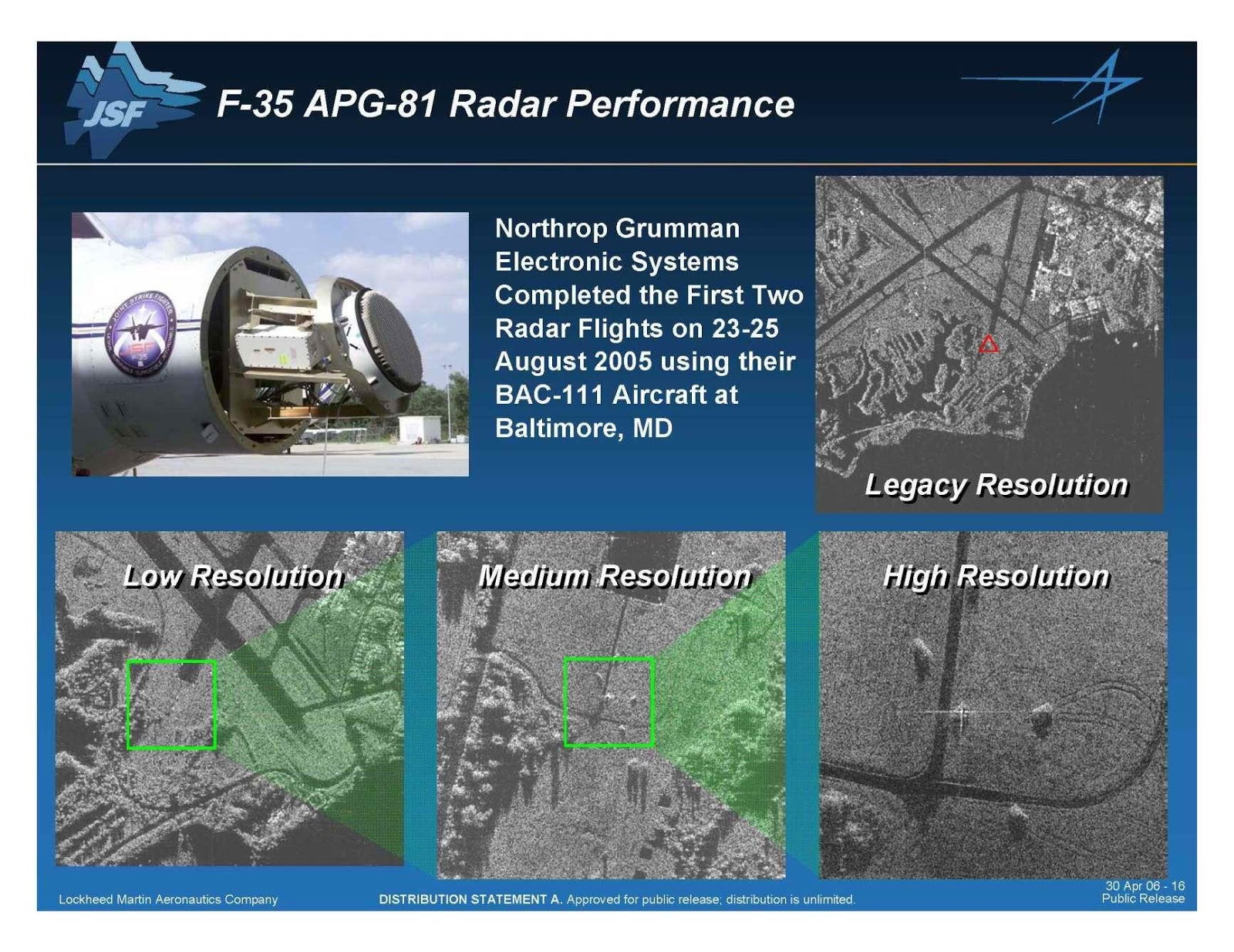
Cutting-edge AESA radar like on the F-35 is incredible. It actually looks like a black and white photograph. I think your guess on antennas is roughly correct based on what we know about modern AESA.
Isn't that Synthetic Aperture Radar though? You can get similar results (black and white aerial pictures) by strapping a pretty basic siso radar system on a drone.
I’m honestly not sure what the difference is. I kind of understand SISO, MIMO, and beam steering concepts, but just the basics from nerding out on my Starlink dish.
This is what I’m talking about: https://www.twz.com/f-35-will-get-new-radar-under-massive-up...
Specifically this image: https://www.twz.com/uploads/2023/01/03/20065813381381024.jpg
I don’t know how targeting works, but with this level of resolution, I think basic image algorithms can start to come into play. It blows my mind.
Yes, that looks like regular SAR imagery. Checkout @umbraspace if you want to see some really nice SAR images captured by satellites launched along starlink satellites.
Wow - that's awesome!
Any idea if these antennas can be made small/on a PCB, effectively miniaturizing them?
Look at the forward looking automotive 4D (distance, speed, azimuth angle, elevation angle) radar systems. The new ones work at around 80GHz, and the entire thing comes in one integrated, tiny package, 16x16 phased array antenna already included with the MCs and FPGAs on the same board.
To go from those 4D radar maps to a voxel system requires a whole lot of software, of course.
The end goal seems to be to beat LIDAR on price and reliability (turns out moving mirrors don't like years of constant vibrations), while delivering enough resolution for self-driving.
Is it legal? I mean, can you just make it and go to the street and play with it?
Henrik Forsten is definitely the coolest radar guy on the internet I'm aware of.
Hats off to you!
Nah w2aew is better
Did you test this with arbitrary waveforms? Is it possible for you to accumulate complementary Golay Codes?
This is really impressive. Do you plan to use it for anything or another project?
I built it to see if I could. I didn't have any particular use case in mind.
Would this be useful for another SAR setup?
I just want to know how much this cost
> Cost was 330 USD for PCB manufacturing and assembly of two PCBs and additional 225 EUR (240 USD) for components from Digikey that I soldered myself. This is including 24% VAT and shipping costs.
Plus the test and validation equipment which are $$$
I actually didn't use any expensive test equipment, only oscilloscope and multimeter. Even design and simulation software was all open source.
Expensive signal analyzer or spectrum analyzer would have been useful, but they aren't absolutely necessary. It's possible to use the radar itself for many tests and debugging.
I have tried to limit the projects I do on my own to only the equipment that I have home and open source software.
Fantastic work! I enjoyed reading the previous posts as well, very interesting.
I came to ask about that 24% VAT - ouch!